3-50
95-8533
18.2
SYSTEM CONFIGURATION
SETTING DEVICE NETWORK
ADDRESSES
Overview of Network Addresses
Each device on the LON must be assigned a
unique address. Addresses 1 to 4 are reserved
for the controller. Valid addresses for field
devices are from 5 to 250.
IMPORTANT
If the address is set to zero or an
address above 250, the communication
module will ignore the switch setting.
Duplicated addresses are not automatically
detected. Modules given the same address
will use the number given and report to the
controller using that address. A "Rogue
Device" message will be displayed when
two LON devices have duplicate addresses
assigned to them. The status word will show
the latest update, which could be from any of
the reporting modules using that address.
Setting Field Device Addresses
Selection of the node address for field devices
is done by setting rocker switches on an
8 switch “DIP Switch” within each device’s
housing.
NOTE
Only the rst eight of the 12 switches are
used for selecting the device address.
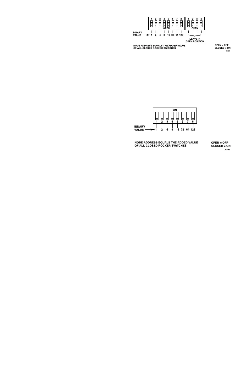
The address number is binary encoded with
each switch having a specific binary value with
switch 1 being the LSB (Least Significant Bit).
(See Figure 3-58) The device’s LON address is
equal to the added value of all closed rocker
switches. All “Open” switches are ignored.
NOTE
The address switches in the DCIO
module and relay module appear slightly
different than those in other devices.
Refer to Figure 3-59.
Example: for node No. 5, close rocker switches
1 and 3 (binary values 1 + 4); for node No. 25,
close rocker switches 1, 4 and 5 (binary values
1 + 8 + 16).
NOTE
The eld device sets the LON address
only when power is applied to the
device. Therefore, it is important to set
the switches before applying power. If an
address is ever changed, system power
must be cycled before the new address
will take effect.
After setting address switches, record the
address number and device type on the
“Address Identification Chart” provided with
this manual. Post the chart in a convenient
location near the Controller for future reference.
Figure 3-58—Field Device Address Switches for
ARM, SAM, DCU and IDC
Figure 3-59—Address Switch for DCIO and Relay Module