95-8533
3-47
18.2
W R O N G
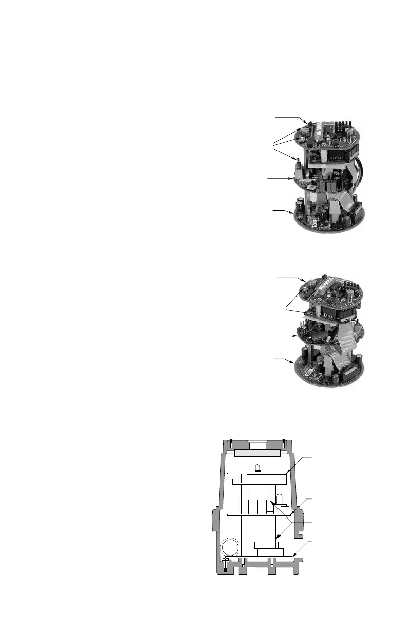
TRANSMITTER BOARD
STANDOFFS (4)
TERMINAL WIRING BOARD
COMMUNICATION MODULE
SWITCHES ON SAME SIDE
(RIGHT)
TRANSMITTER BOARD
TERMINAL WIRING BOARD
CORRECT ORIENTATION OF TRANSMITTER BOARD
COMMUNICATION MODULE
SWITCHES ON OPPOSITE SIDES
(WRONG)
TRANSMITTER BOARD
TERMINAL WIRING BOARD
INCORRECT ORIENTATION OF TRANSMITTER BOARD
B1570
Figure 3-55—Printed Circuit Boards in Combustible Gas DCU
11. Inspect the junction box O-ring to be sure
that it is in good condition. Lubricate the
O-ring and the threads of the junction
box cover with a thin coat of silicone-free
grease (available from Det-Tronics).
12. Replace the device cover.
Sensor Separation with DCUEX
If the installation requires mounting the sensor
in a different location than the DCUEX, observe
the following guidelines.
There are two methods that can be used to
separate the sensor from the DCUEX:
Preferred Method
1. Disassemble the DCUEX and remove
the transmitter board. (Refer to “Wiring”
for disassembly procedure.) Do not re-
assemble at this time.
2. Mount the transmitter board inside the
sensor separation junction box (remove the
existing board).
NOTE
This assembly can be separated from
the DCUEX by up to 1000 feet using
three conductor 18 AWG shielded cable.
(Regardless of separation distance,
operating voltage at the transmitter must
be at least 18 Vdc for proper device
operation.) (See Figure 3-56.)
3. Mount the sensor to the separation junction
box. DO NOT overtighten. Plug the sensor
into P2 on the transmitter board.
4. Use a three conductor 18 AWG shielded
cable to connect P1 on the transmitter
board to terminals 2, 3 and 4 on the DCU
terminal board (See Figure 3-56). Connect
the shield to the ground terminal in the
DCUEX junction box.
5. Connect all external wiring to the terminal
wiring board inside the DCU (if not already
completed). Re-assemble the DCUEX as
described in the “Wiring” section. When
completed, it should look similar to the DCU
as shown in Figure 3-50.
6. Inspect the O-ring on the DCU and
separation junction box to be sure that
they are in good condition. Lubricate the
O-ring and the threads of the junction box
cover with a thin coat of silicone-free grease
(available from Det-Tronics).
7. Replace the cover on the DCU and
separation junction box.