95-8533
2-11
18.2
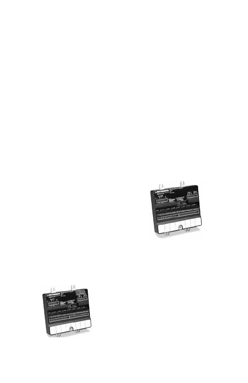
EQ3700 8 Channel DCIO Module
The 8 Channel Discrete Input/Output (DCIO)
Module (see Figure 2-11) consists of eight
individually configured channels. Each channel
is configured as either an input or output with
the appropriate wiring supervision. Wiring
supervision includes none, open circuits, and
"open and short" circuits. In addition to defining
the type of supervision, an input channel is also
configured to generate the appropriate static
logic alarm message to the controller.
NOTE
NFPA 72 requires wire supervision
selection for fire detection and
notification devices (IDC, NAC,
supervisory and releasing devices).
Heat, smoke, or unitized flame detectors can
be wired into channels defined as inputs.
Horns and strobes/beacons can be wired into
channels defined as outputs.
NOTE
The DCIO outputs only support
equipment that operates on 24 vdc (not
to exceed 2 amperes per channel).
The DCIO has two device status LEDs, as well
as two LEDs for each channel. On the device
level, one green LED indicates power, while
the other amber LED indicates a LON CPU
fault. For each channel, one red LED indicates
channel activation and the other amber
LED indicates a fault condition when wiring
supervision is defined for the channel.
Refer to the DCIO Specification Data sheet
(form number 90-1149) for additional
information.
Figure 2-11—DCIO Module
EQ3720 8 Channel Relay Module
The 8 Channel Relay Module (see Figure 2-12)
consists of eight individually configured output
channels.
NOTE
The relay module supports equipment
that operates on:
24 Vdc (not to exceed 1 amperes)
The relay module has two LEDs for the device
and two LEDs for each channel. On the device
level, one green LED indicates power, while
the other amber LED indicates a LON CPU
fault. For each channel, one red LED indicates
channel activation and the other amber LED
indicates that the module operating voltage is
low or that the module has not been configured
(all eight channel LEDs blink).
Refer to the Relay Module Specification Data
sheet (form number 90-1181) for additional
information.
Figure 2-12—Eight Channel Relay Module