95-8533
4-11
18.2
ENHANCED DISCRETE I/O
MODULE
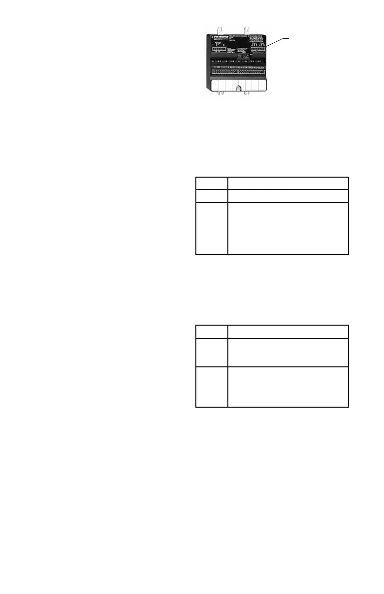
The EDIO Module (see Figure 4-6) has 18 LED
status indicators, two for the device and two
for each channel, located on the front panel.
Refer to Tables 4-7 and 4-8 for a description of
the LED indicators.
POWER-UP SEQUENCE
Set the module address switch prior to applying
power.
EDIO module power-up sequence illuminates
the LEDs for the device and all of its channels.
First the power and fault LEDs are illuminated,
indicating that the device is in a power-up
mode. Next the LEDs are illuminated in the
following sequences:
• Sequentially each channel active red LED
is illuminated, starting with channel 1 and
continuing through channel 8.
• When the red LED for channel 8 is
illuminated, sequentially each channel
active red LED is turned off, starting with
channel 1 and continuing through channel
8.
• Next, the channel fault amber LEDs are
tested in the same manner as the channel
active red LEDs.
When all the LEDs have been illuminated,
the EDIO module displays the device’s LON
address by illuminating the channel active
red LED. LON dip switches 1 though 8 will be
displayed on channels 1 through 8. When a
dip switch is set to the ON position, the channel
active red LED will be illuminated. The address
is displayed for two seconds.
Once the address has been displayed, the
device’s fault LED will turn off.
After the power-up sequence, the device will
either display an unconfigured state or normal
operation state. In the unconfigured state, the
channel fault amber LEDs flash ON and OFF at
the same rate for all channels.
STATUS INDICATOR LEDs
Figure 4-6—EDIO Module Status Indicator Location
Table 4-7—EDIO Module - Device Status Indicators
Table 4-8—EDIO Module - Channel Status Indicators
LED Device Status
Green On when power is present.
Amber When On steady indicates device
is disabled or must be replaced.
Possible Watchdog Timer problem.
NOTE
Blinks one time at power-up.
LED Channel Status
Red When On steady indicates the input
circuit is closed or the output circuit
is active
Amber When Blinking indicates a low power
condition is present or channel is not
properly configured. Steady indicates
a channel fault.