95-8533
3-29
18.2
NOTE
For additional information, refer to the
power supply manufacturer’s documents
provided with the support documentation
received with the Eagle Quantum
Premier system.
STARTUP
Turn on the power supply and allow the voltage
to stabilize. Verify the output voltage and adjust
as needed. Refer to "EQP2XX0PS(–X) Power
Supplies" in the Specifications section of this
manual.
IMPORTANT
The output voltage is adjustable. An even
current distribution must be ensured by
precisely setting all power supply units
that are operated in parallel to the same
output voltage ±10 mV.
IMPORTANT
To ensure symmetrical current
distribution it is recommended that all
cable connections from all power supply
units/diode redundancy modules to the
power distribution bus are the same
length and have the same cross section.
ENHANCED DISCRETE
INPUT/OUTPUT (EDIO)
MODULE INSTALLATION
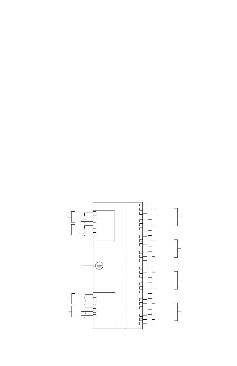
All electrical connections are made to the field
wiring connectors furnished with the module.
Refer to Figure 3-23 for identification of module
wiring terminals.
Connector P1, Terminals 1 to 6
24 Vdc Power Input
Connect the module power supply to terminals
1 and 2. If additional terminals are required for
powering other devices, these devices should
be connected to terminals 4 and 5. Shields
are to be connected to terminals 3 and 6 —
chassis (earth) ground terminals. Total output
current should be limited to 10 amperes.
Connector P2, Terminals 1 to 6
LON/SLC Signaling Circuit Terminals
Be sure to observe polarity when wiring the
LON/SLC.
1 — "A" side of signaling circuit for COM 1
2 — "B" side of signaling circuit for COM 1
4 — "A" side of signaling circuit for COM 2
5 — "B" side of signaling circuit for COM 2
3, 6 — shield connection
CHANNEL 8
CHANNEL 7
CHANNEL 6
CLASS A
CHANNEL
CLASS A
CHANNEL
CLASS A
CHANNEL
CLASS A
CHANNEL 1
CHANNEL 5
CHANNEL 4
CHANNEL 3
CHANNEL 2
CHANNEL 1
COM
6
5
4
3
2
1
COM 2 SHLD
COM 2 B
COM 2 A
COM 1 SHLD
COM 1 B
COM 1 A
SHLD
B
A
SHLD
B
A
LON FROM
PREVIOUS DEVICE
LON TO
NEXT DEVICE
POWER
6
5
4
3
2
1
SHLD
–
+
SHLD
–
+
SHLD*
–
+
SHLD
*
–
+
24 VDC
INPUT VOLTAGE
24 VDC
INPUT VOLTAGE
EQ3730EDIO
TO
EARTH
GROUND
+ SUPPLY A
IN–/OUT+ B
COMMON C
+ SUPPLY A
IN–/OUT+ B
COMMON C
+ SUPPLY A
IN–/OUT+ B
COMMON C
+ SUPPLY A
IN–/OUT+ B
COMMON C
+ SUPPLY A
IN–/OUT+ B
COMMON C
+ SUPPLY A
IN–/OUT+ B
COMMON C
+ SUPPLY A
IN–/OUT+ B
COMMON C
+ SUPPLY A
IN–/OUT+ B
COMMON C
1
2
3
4
5
6
7
8
9
10
11
12
13
14
15
16
17
18
19
20
21
22
23
24
* SHIELDS ON POWER WIRES ARE OPTIONAL
UNLESS REQUIRED BY LOCAL CODES.
Figure 3-23—EDIO Module Wiring Terminals