95-8533
3-33
18.2
this wire length includes both the wiring from
the power supply to the EDIO module and the
wiring from the module to the solenoid.)
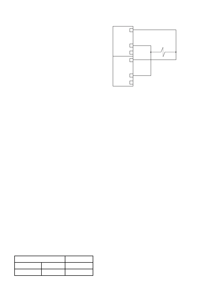
Supervised Output for Deluge
and Pre-action
The maximum wiring length must not exceed
the values shown in Table 3-10 for deluge
and pre-action applications. Per FM Approval
requirements, the secondary power must
provide capacity for a 90 hour minimum
standby operation followed by a minimum of
10 minutes of releasing and alarm operation.
The initiating device circuit(s) for use
with the deluge and pre-action system
conguration must use Class A wiring or
be wired in conduit within 20 feet from the
EDIO.
NOTE
In EQP systems with EQP2120PS(–B)
Power Supplies, the secondary power
is customer supplied and must be
accepted by the Authority Having
Jurisdiction (AHJ).
CONFIGURATION
Setting EDIO Network Address
One unique network address must be assigned
to each EDIO module. The address is set by the
8 switch DIP assembly on the EDIO module.
When using the switches located on the EDIO
module, the address is binary coded and is
the sum of all switches placed in the “closed”
position.
Each discrete point of an EDIO module has
a tag number and a descriptor for unique
identification. A tag number must include
zone designation, which will be shown on the
controller's display when the point is in alarm.
Det-Tronics S
³
Safety System Software is used
for device configuration. The following shows
the minimum software/firmware releases:
Controller Firmware S
³
Revision Version Version
B 4.28 3.1.0.0
8 CHANNEL DISCRETE
INPUT/OUTPUT (DCIO)
MODULE INSTALLATION
The following paragraphs describe how to
properly install and configure the 8 Channel
DCIO Module.
MOUNTING
The DCIO must be properly installed in a
suitable enclosure that is rated for the location.
The enclosure must provide space to install and
wire the DCIO module and must also provide
for ground wire termination. Access into the
enclosure is gained by using a special tool to
open the enclosure. The enclosure should be
rated for the temperature range of the location
plus the temperature rise of all equipment
installed inside the enclosure. The enclosure
must be rated for electrical equipment that is
going to be installed.
The DCIO can be panel or DIN rail mounted.
NOTE
It is recommended to maintain a
minimum of four inches clearance
between the module and other
equipment to provide adequate room for
wiring and ventilation.
+ SUPPLY A
IN– / OUT+ B
COMMON C
1
2
3
+ SUPPLY A
IN– / OUT+ B
COMMON C
4
5
6
NOTE: SHUNT/FLYBACK DIODES DO
NOT NEED TO BE INSTALLED
ON THE FIELD DEVICE.
CIRCUIT PROTECTION IS
PROVIDED WITHIN THE
EDIO MODULE.
B2286
Figure 3-35—Supervised Output Conguration (Agent
Release)— Class A Wiring