3-32
95-8533
18.2
Supervised Output—
Notication Supervised for Open & Short
Circuits
Connect external system wiring to the
appropriate terminals on the terminal block.
For Class B wiring, refer to Figure 3-32.
For Class A wiring, refer to Figure 3-33. Note
that two channels are used for one output
circuit.
The output of the EDIO module supervises
the notification circuit by reversing the polarity
of the monitoring circuit. Polarity must be
observed when connecting the notification
device. It is essential to utilize a notification
device approved for fire alarm notification.
These devices are polarized and would not
require the use of an external diode for the
supervision of the circuit. Wire one or more
notification devices to the output, with a 10 K
ohm, 1/4 watt EOL resistor in parallel across
the last device.
No connection should be made to “+ Supply”
terminal.
Each output channel is individually activated
for response pattern:
– supervisory
– continuous output
– 60 beats per minute
– 20 beats per minute
– temporal
– timed
– trouble.
Supervised Output—
Agent Release (Solenoid Circuit)
Connect external system wiring to the
appropriate terminals on the terminal block.
For Class B wiring, refer to Figure 3-34.
For Class A wiring, refer to Figure 3-35. Note
that two channels are used for one output
circuit. Trouble indication is provided for any
open wire and the output can still be activated
with a single open wire.
No connection should be made to “+ Supply”
terminal.
The output of the EDIO module supervises the
releasing circuit via the coil of the releasing
solenoid. It is essential to utilize a releasing
device approved for use with this output
module. This type of output does not require
the use of EOL resistors or diodes to supervise
the circuit.
The output can be configured for latching,
continuous, supervisory, trouble or timed
response.
To ensure adequate operating voltage for the
output device, the maximum wiring length from
the power source to the output device must
not exceed the values shown in Table 3-10 for
automatic release applications. (For solenoids,
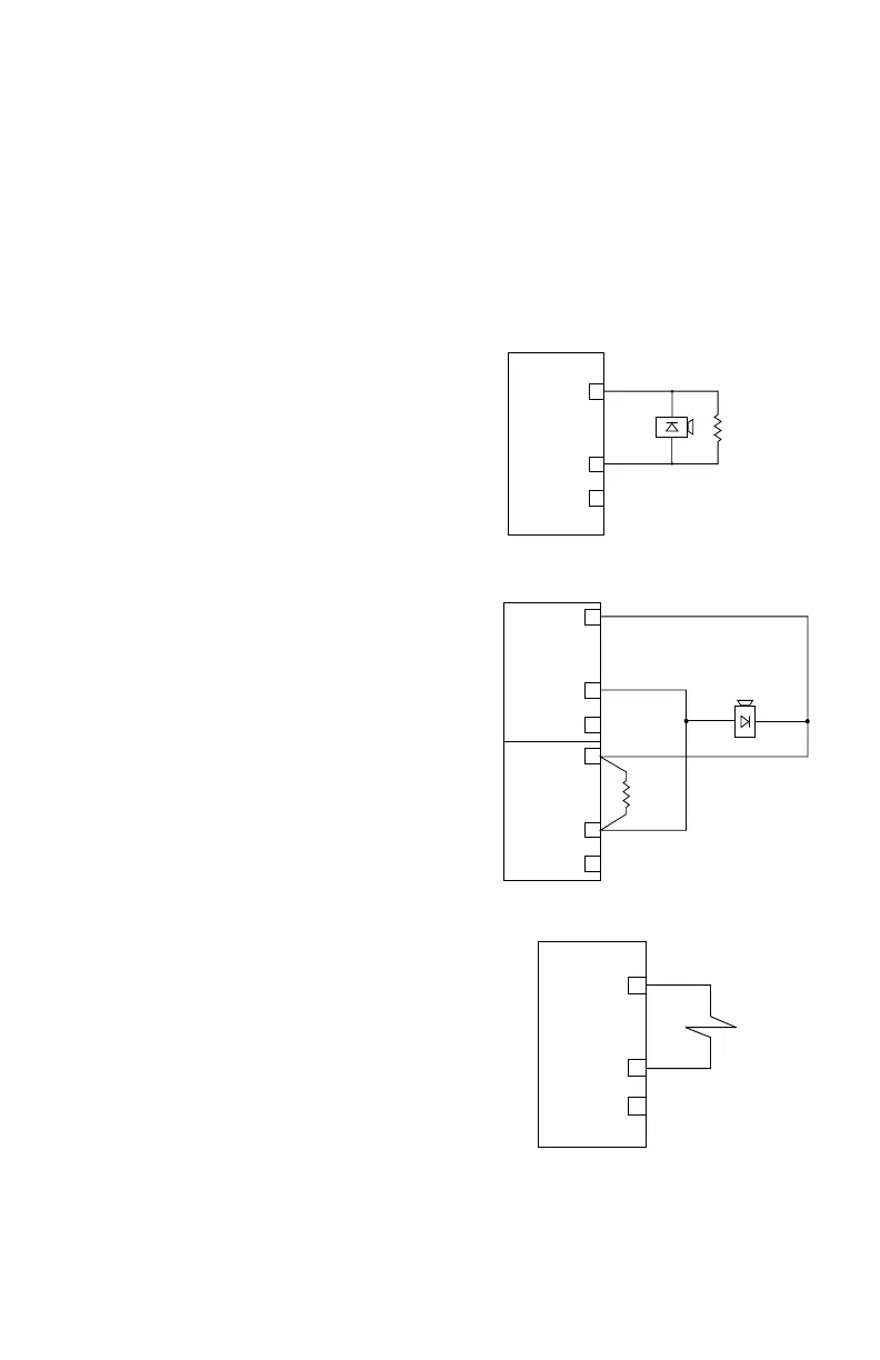
+ SUPPLY A
IN– / OUT+ B
COMMON C
1
2
3
EOL
RESISTOR
10 K Ω
Figure 3-32—Supervised Output Conguration
(Notication)— Class B
+ SUPPLY A
IN– / OUT+ B
COMMON C
1
2
3
NOTE: SHUNT/FLYBACK DIODES DO NOT NEED
TO BE INSTALLED ON THE FIELD DEVICE.
CIRCUIT PROTECTION IS PROVIDED
WITHIN THE EDIO MODULE.
A2322
Figure 3-34—Supervised Output Conguration
(Agent Release)
+ SUPPLY A
IN– / OUT+ B
COMMON C
1
2
3
+ SUPPLY A
IN– / OUT+ B
COMMON C
4
5
6
A2285
EOL
RESISTOR
10 K Ω
Figure 3-33—Supervised Output Conguration
(Notication)— Class A