95-8533
2-3
18.2
THEORY OF OPERATION
During normal operation, the Controller
continuously checks the system for fault
conditions and executes user defined
programmed logic that coordinates the control
of the field devices. At the same time, the field
devices are continuously monitoring for device
based fault and alarm conditions.
When a fault condition occurs, the Controller
displays the fault condition on the Vacuum
Fluorescent Text Display, activates the
appropriate fault LED(s), activates the Trouble
signal using the Controller’s internal enunciator,
and de-energizes the Controller’s Trouble relay.
Controller based fault conditions include the
Controller status and LON communications
such as the heartbeat being sent around
the loop and the field device loss of
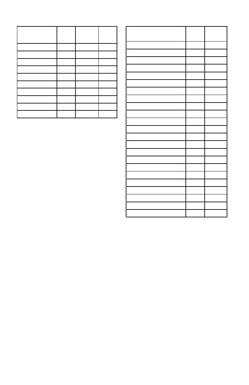
communications. Controller based fault
conditions are listed in Table 2-1.
Field device based fault conditions are
transmitted to the Controller, where they are
then annunciated. Refer to Table 2-2 for a
listing of field device faults. Each field device
transmits its status to the Controller on a
regular basis.
When an alarm condition occurs, the Controller
displays the alarm condition on the text display,
activates the appropriate Alarm LED(s), and
activates the alarm signal using the Controller’s
internal annunciator.
Controller Faults
Shown on Text
Display
Trouble
LED
LON Fault
LED
Trouble
Relay
Controller Fault
x x
Device Offline
x x
Extra LON Device
x x
Invalid Config
x x
Lon Fault
x x x
LON Ground Fault
x x
Power Fail 1
x x
Power Fail 2
x x
RTC Fault
x x
Redundancy Fault*
x x
Field Device Faults
Shown on Text Display
Trouble
LED
Trouble
Relay
290 Volt Fault X X
AC Failed X X
Battery Fault X X
Beam Block X X
Calibration Fault X X
Channel Open X X
Channel Short X X
Dirty Optics X X
Ground Fault Negative X X
Ground Fault Positive X X
IR Auto Oi Fault X X
IR Fault X X
IR Manual Oi Fault X X
Low Aux Power Fault X X
Missing IR Sensor Fault X X
Missing UV Sensor Fault X X
Power Supply Fault X X
Sensor Fault X X
Supply Voltage Fault X X
Tx Lamp Fault X X
UV Auto Oi Fault X X
UV Fault X X
UV Manual Oi Fault X X
Table 2-1—Controller Based Faults
*Only for controller pair congured for redundancy.
Table 2-2—Field Device Based Faults