4-6
95-8533
18.2
Lon Comm
Redundant controllers exchange information
across the LON network. This is primarily done
to prevent both controllers from becoming the
master in the event that the HSSL fails. The fault
is annunciated when a controller fails to receive
any information from the other controller.
Msg Error
If the standby controller receives a message
from the master that has the correct CRC but
invalid data an error message is returned. This
master will indicate the error with this fault.
Program Flow
Program flow checking ensures that essential
functions execute in the correct sequence.
If any functions don’t execute properly, or
execute in the wrong order, the program flow
error is set and control is transferred to the
standby controller.
LON A/B Inf
Controllers utilize neuron co-processors to
interface with the field device network. If an
error is detected in the operation of the co-
processor, a LON interface fault is annunciated.
User Logic CS
Controllers continually conduct a checksum
test of the user logic program to ensure that the
data remains unchanged. A user checksum
fault is annunciated if the result is incorrect.
App CS
When the controller firmware is generated a
checksum of the program is calculated and
saved in memory. Each controller is continually
conducting a checksum test of the program to
ensure that the data remains unchanged. The
application checksum fault is annunciated if
the result is incorrect.
User Logic
Many checks are conducted while the controller
interprets and executes the user program. The
user logic error is generated if invalid or out of
range data is detected.
Cong
This fault is annunciated when a controller
has not been configured or the configuration
information has been corrupted.
Power 1
Displays the power 1 status on the standby
controller.
Power 2
Displays the power 2 status on the standby
controller.
Option Bd
Indicates whether there is a fault on the
ControlNet or EtherNet DLR option board of the
standby controller.
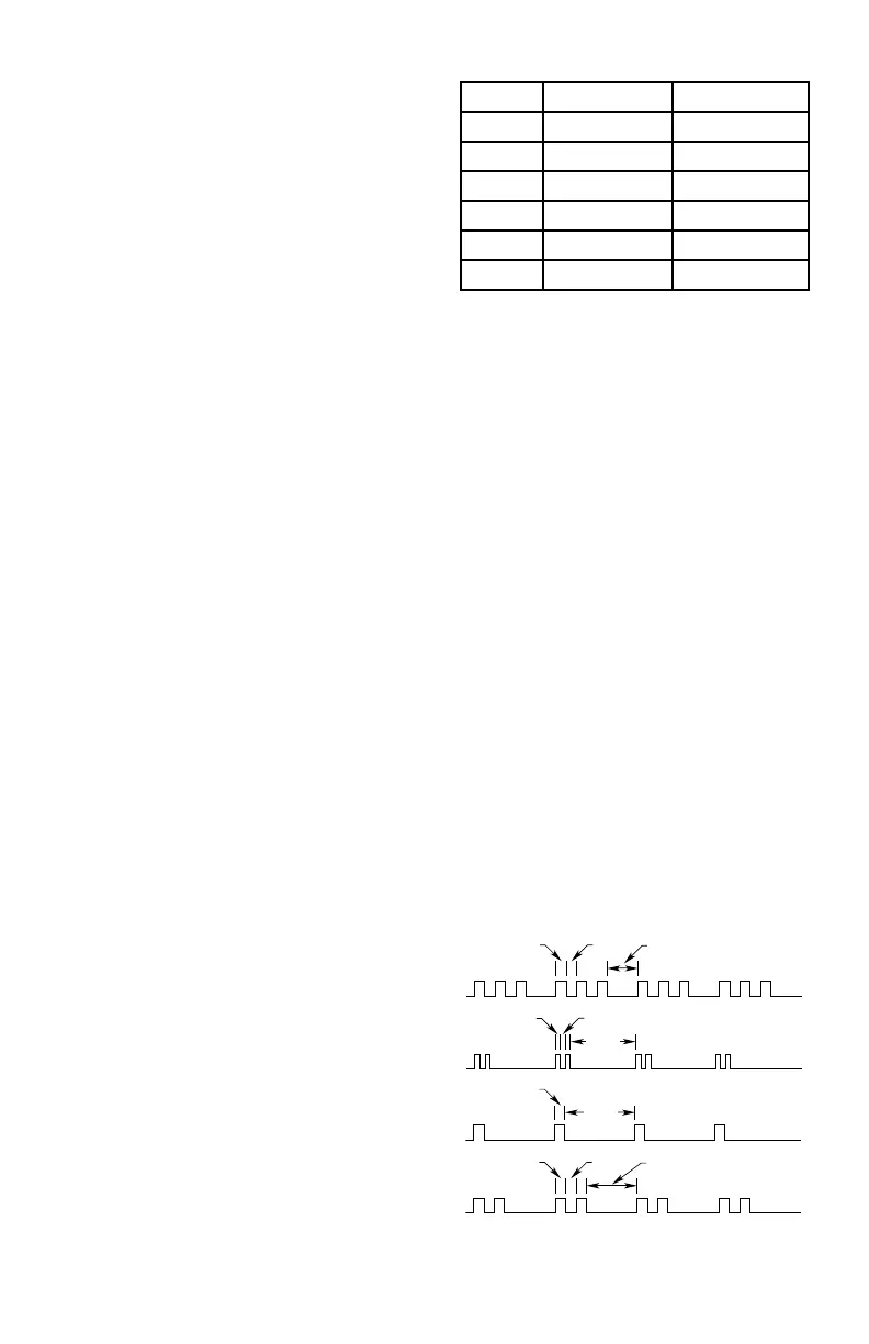
CONTROLLER AUDIBLE ALARM
The Controller features an internal audible
alarm for local system status notification (see
Table 4-2 and Figure 4-4). When the system
is operating in the normal mode (no Alarm or
Fault conditions occurring), the alarm is silent
(off). If an event (any alarm or trouble condition)
occurs, the alarm will remain active until it is
acknowledged by pressing the Acknowledge
pushbutton or reset by pressing the Reset
pushbutton on the Controller front panel.
NOTE
If multiple alarms exist, “Acknowledging”
will silence the audible alarms.
Table 4-2—EQP Controller Alarm Tone Patterns
Priority Controller Tone Tone Pattern
1 Fire Alarm Temporal
2 Supervisory Supervisory
3 Trouble Trouble
4 High Gas Gas
5 Low Gas Gas
6 Normal Off
0.5 SEC 0.5 SEC
1.5 SEC
FIRE
ALARM
0.5 SEC 0.5 SEC
3.0 SEC
HIGH/LOW
GAS
0.5 SEC
5.0 SEC
TROUBLE
0.1 SEC
0.1 SEC
2.0 SEC
SUPERVISOR
B1855
Figure 4-4—Tone Pattern for Controller Buzzer