95-8533
3-45
18.2
Sensor Separation for DCU with H2S
and O2 Sensors
Since the transmitter for the electrochemical
sensor is already mounted within the sensor
housing, simply mount the entire sensor
assembly to the sensor separation kit junction
box and wire it to terminals 2 and 4 inside the
DCU, the same as a regular (without sensor
separation) installation. Connect the shield to
the ground terminal in the DCU junction box.
Refer to Table 3-12 for separation distance
limitations for H2S and O2 sensors
EQ22XXDCU DIGITAL COMMUNICA-
TION UNIT USED WITH POINTWATCH/
DUCTWATCH
Determine the best mounting location for the
detector. Whenever practical, detectors should
be placed where they are easily accessible for
calibration.
WARNING
Do not apply power to the system with
the cover removed unless the area has
been veried to be free of combustible
gases and vapors.
The DCU utilizes the following:
1. A terminal wiring board mounted at the
bottom of the junction box.
2. A communication module mounted above
the terminal wiring board using the standoffs
provided. See Figure 3-50.
Assembly and Wiring Procedure
Attach the PointWatch/DuctWatch to the DCU
enclosure. Do not over-tighten. If a sensor
separation kit is being used, attach the sensor
to the separation kit junction box and wire the
device as described in the “Sensor Separation”
section.
Refer to the PointWatch instruction manual
(form number 95-8440) or the DuctWatch
instruction manual (form number 95-8573)
for complete installation and application
information.
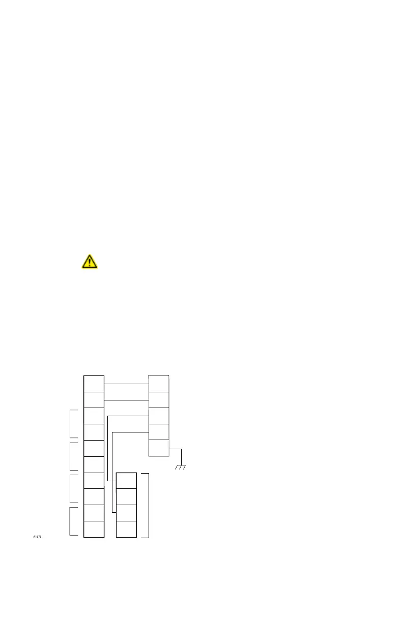
Refer to Figure 3-53 when wiring a PointWatch
IR gas detector and a DCU. The wiring code
for PointWatch is:
Red = + (24 Vdc)
Black = – (common)
White = 4 to 20 mA signal
Yellow = Calibration input
Green = Chassis ground
Set the address for the device. Refer to
“Setting Device Network Addresses” for
complete information regarding the switch
setting procedure.
Sensor Separation for DCU
with PointWatch
Shielded four wire cable is recommended for
connecting the detector junction box to the
DCU. Cable with a foil shield is recommended.
The shield of the cable should be open at the
detector junction box and connected to earth
ground at the DCU junction box.
NOTE
To ensure proper operation, it is
essential to maintain a minimum of 18
Vdc (including ripple) at the PointWatch
detector.
1
2
3
4
5
6
7
8
9
10
YELLOW
WHITE
BLACK
RED
GREEN
DCU POINTWATCH
14
13
12
11
–
–
+
+
24 VDC
POINTWATCH CALIBRATE
4 TO 20 MA IN
–
+
A
B
A
B
SENSOR POWER
COM 2
COM SHIELD
COM 1
Figure 3-53—PointWatch/DuctWatch Connected to DCU