3-44
95-8533
18.2
See Figure 3-52 for an example of a Det-Tronics
electrochemical sensor connected to a DCU.
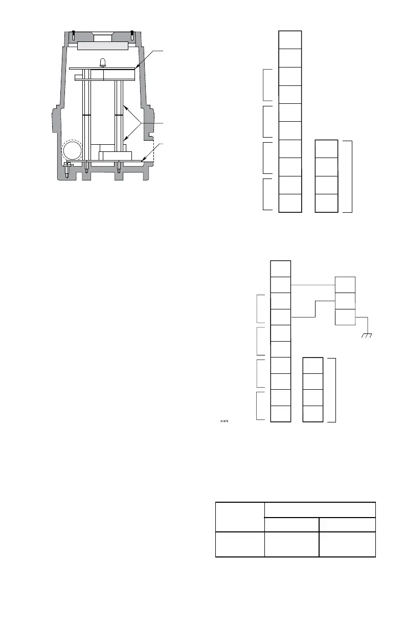
Attach the communication module to the
standoffs as shown in Figure 3-48. Connect the
ribbon cable from the terminal wiring board to
the communication module.
Set the address for the device. Refer to
“Setting Device Network Addresses” for
complete information regarding the switch
setting procedure.
Check the wiring to ensure proper connections,
then pour the conduit seals and allow them to
dry (if conduit is being used).
NOTE
Before placing the cover back on the
enclosure following completion of
assembly and wiring, inspect the
enclosure O-ring to be sure that it is in
good condition and properly installed.
Lubricate the O-ring and the threads
of the cover with a thin coat of an
appropriate grease to ease installation.
Refer to the “Ordering Information”
section for the part number of the
recommended grease (available from
Detector Electronics). If the installation
uses catalytic type combustible gas
sensors, it is imperative that lubricants
containing silicone not be used, since
they will cause irreversible damage to the
sensor. Place the cover on the enclosure.
Tighten only until snug. Do not over
tighten.
A1571
COMMUNICATION
MODULE
STANDOFFS (4)
TERMINAL
WIRING BOARD
Figure 3-50—Printed Circuit Boards in Universal DCU
1
2
3
4
5
6
7
8
9
10
14
13
12
11
–
–
+
+
24 VDC
POINTWATCH CALIBRATE
4 TO 20 MA IN
–
+
A
B
A
B
SENSOR POWER
COM 2
COM SHIELD
COM 1
Figure 3-51—Wiring Conguration for DCU
1
2
3
4
5
6
7
8
9
10
BLACK
RED
GREEN
2
2
14
13
12
11
–
–
+
+
24 VDC
POINTWATCH CALIBRATE
4 TO 20 MA IN
–
+
A
B
A
B
SENSOR POWER
COM 2
COM SHIELD
COM 1
Figure 3-52—Electrochemical Sensor Connected to DCU
Table 3-12
Maximum Separation Distances —
Electrochemical Sensor to DCU
T0020A
Wire Size Maximum Wiring Distance
(AWG) Feet Meters
18 5700 1750
16 9000 2800