95-8533
3-8
18.2
CAUTION
ALWAYS discharge static charges
from hands before handling electronic
devices or touching device terminals.
Many devices contain semiconductors
that are susceptible to damage by
electrostatic discharge.
NOTE
For more information on proper handling,
refer to Det-Tronics Service Memo form
75-1005.
GROUND FAULT MONITOR
(GFM) INSTALLATION
Mounting
The GFM is a DIN rail mountable device
designed to be mounted in the same enclosure
as the EQP controller.
Wiring
1. Connect power wiring from the EQP
controller power terminals 1 and 2 to the
GFM terminals 1 and 2.
2. Connect power wiring from the GFM
terminals 3 and 4 to the EQP controller
power terminals 3 and 4.
3. Connect earth ground to terminal 5 or 10.
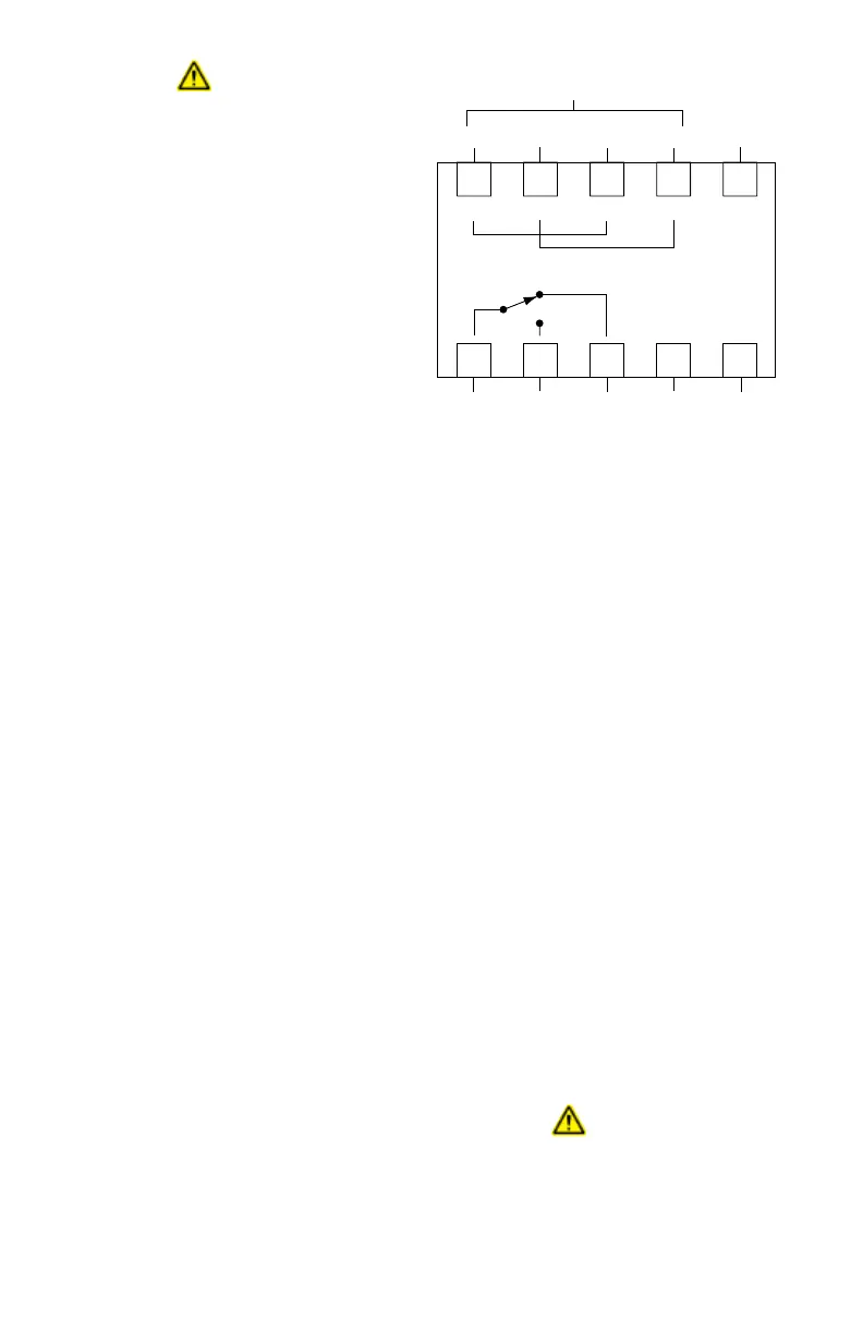
4. Connect the relay contacts as required.
Refer to Figure 3-1 for terminal block
identification.
NETWORK AND NETWORK
EXTENDER INSTALLATION
Mounting
The device should be securely mounted to a
vibration free surface. (See the “Specifications”
section in this manual for device dimensions.)
Wiring
All devices on the LON are wired in a loop that
starts and ends at the System Controller. To
ensure proper operation, the LON should be
wired using high speed communication grade
cable.
NOTE
Cable meeting the specications listed in
Table 3-6 is suitable for distances up to
2000 meters.
Any of the cable types listed in Table 3-7 can
be used for wiring the LON for the distances
indicated.
NOTE
If no network extenders are used, the
distances listed are for the entire loop.
If network extenders are used, the
distances listed are for the wiring length
between network extenders or between
a network extender and the System
Controller.
IMPORTANT
Det-Tronics recommends the use of
shielded cable (required by ATEX)
to prevent external electromagnetic
interference from affecting eld devices.
WARNING
Be sure that the selected cable meets
all job specications and is rated for the
installation per local and national codes
and practices. The use of other cable
6
7
8
9
10
COMMON NO NC N/C
RELAY
SPARE
1
2
3
4
5
++
EARTH
GROUND
++
EARTH
GROUND
24 VDC
INPUT VOLTAGE
NOTE: RELAY CONTACTS ARE SHOWN IN THE REST STATE,
NO POWER APPLIED. RELAY IS ENERGIZED WITH
POWER APPLIED AND NO GROUND FAULT
(TERMINALS 6 & 7 CLOSE, TERMINALS 6 & 8 OPEN).
Figure 3-1—Terminal Conguration for Ground Fault Monitor