3-22
95-8533
18.2
EQ3XXX REDUNDANT
CONTROLLER
INSTALLATION
The redundant controllers must be purchased
with the following options for correct installation:
• Either Ethernet or Serial Interface Board
• High-speed serial cable
• LON termination modules (2).
ENCLOSURE REQUIREMENTS
The redundant controllers must be located
next to each other in the same enclosure (4 ft
interconnecting cable).
MOUNTING
The controllers are designed for direct
panel mounting or DIN rail mounting. See
“Specifications” section of this manual for
mounting dimensions.
WIRING
The redundant controllers are wired the same
as a simplex controller except for the LON
wiring and the dedicated high-speed serial
link, which are defined below. Refer to EQ3XXX
Controller Installation for general installation
details.
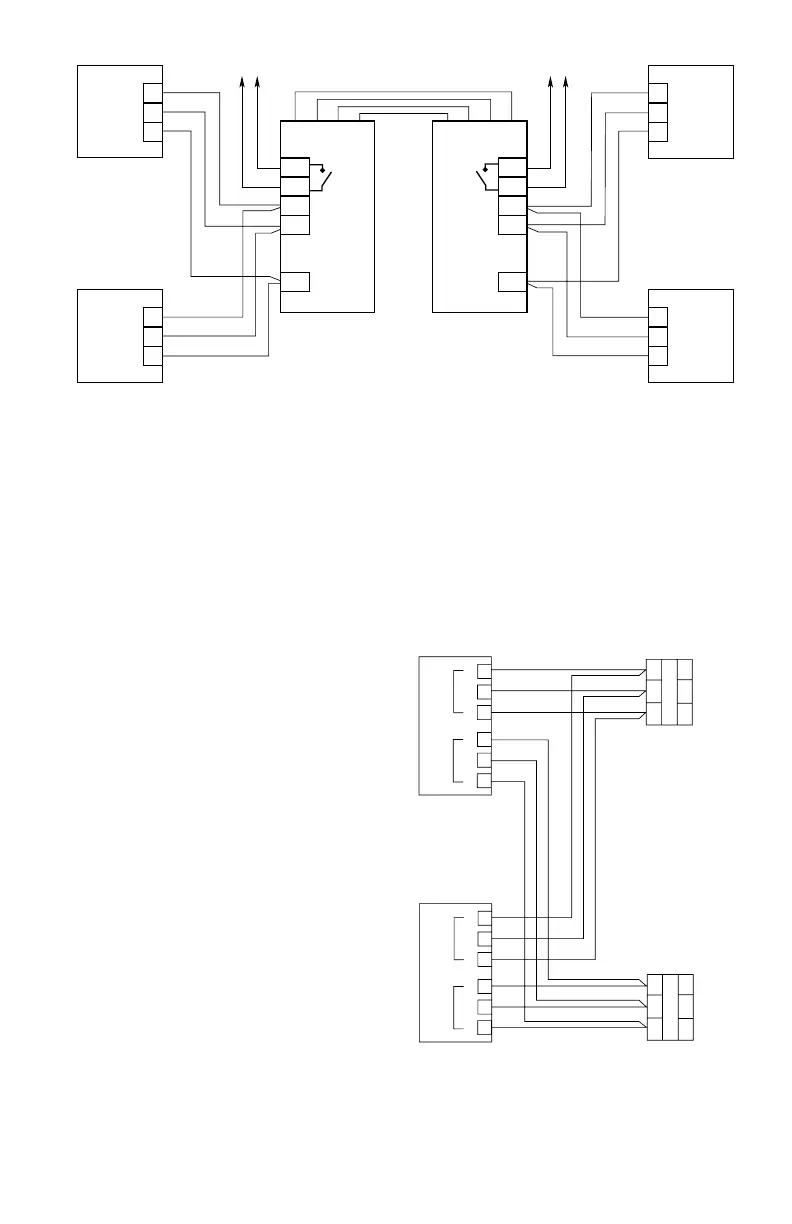
LON WIRING
The LON must be connected to both redundant
controllers to ensure correct operation. Two
LON Termination Modules are required for the
installation as shown in Figure 3-15.
C2274
A
B
S
COM 2
A
B
S
COM 1
EQP
CONTROLLER
53
52
51
50
49
48
A
B
S
COM 2
A
B
S
COM 1
EQP
CONTROLLER
53
52
51
50
49
48
LON TERMINATION JUMPERS P25 AND P26 (SEE FIGURE 3-12)
MUST BE IN POSITION 2 AND 3 FOR REDUNDANT CONFIGURATION
(ON BOTH CONTROLLERS).
LON
TERMINATION
MODULE
A3
2
1
6
5
4
B
S
COM 2 TO
FIELD
DEVICES
LON
TERMINATION
MODULE
A3
2
1
6
5
4
B
S
COM 1
FIELD
DEVICES
Figure 3-15— LON Connection for Redundant EQP
Controllers
PORT 2
RS-485
A
B
GND
60
61
62
PORT 2
RS-485
60
61
62
A
B
GND
CONTROLLER No. 2
PORT 2
RS-485
60
61
62
A
B
GND
PORT 2
RS-485
60
61
62
A
B
GND
EQP CONTROLLER No.
D(P)
D(N)
GND
BRDBTDARDATD ARDATDBRDBTD
Phoenix
PSI-MOS-
RS485W2/FO
Phoenix
PSI-MOS-
RS485W2/FO
D(P)
D(N)
GND
FIBER OPTIC CABLE
B2372
MULTI MODE
TO EQP SYSTEM
TO EQP SYSTEM
Figure 3-14—Multi-Mode Controller to Controller NFPA 72 Approved Fiber Optic Link, Class X