95-8533
3-41
18.2
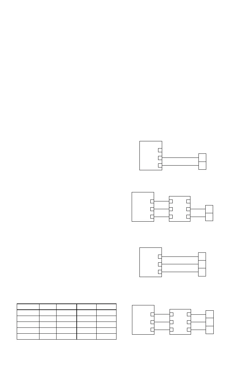
+ SUPPLY A
4-20 MA IN B
COMMON C
CHANNEL 1
1
2
3
A2235
+
SIG
TRANSMITTER
Figure 3-46—Two-Wire Transmitter — Non-Isolated 4 to 20 mA
Current Output (Sourcing)
+ SUPPLY A
4-20 MA IN B
COMMON C
CHANNEL 1
1
2
3
A2236
+
–
SIG
TRANSMITTER
Figure 3-48—Three-Wire Transmitter — Non-Isolated 4 to 20
mA Current Output (Sourcing)
+ SUPPLY A
4-20 MA IN B
COMMON C
CHANNEL 1
1
2
3
+ SUPPLY
4-20 MA IN
COMMON
HIM
14
25
36
A2238
+
SIG
TRANSMITTER
Figure 3-47—Two-Wire Transmitter with HART Interface
Module — Non-Isolated 4 to 20 mA Current Output (Sourcing)
+ SUPPLY A
4-20 MA IN B
COMMON C
CHANNEL 1
1
2
3
A2239
+
–
SIG
TRANSMITTER
+ SUPPLY
4-20 MA IN
COMMON
HIM
14
25
36
Figure 3-49—Three-Wire Transmitter with HART Interface
Module — Non-Isolated 4 to 20 mA Current Output (Sourcing)
Table 3-11—
Analog Values (in mA) for Fault and Status Indications when
the AIM is Used as a 4-20 mA Flame Detector Input
Status X3301/2 X5200 X9800 X2200
Fault 0-3.5 0-3.5 0-3.5 0-3.5
IR Pre-Alarm
7.0-9.0
UV Alarm
11.0-12.99
IR Alarm
13.0-14.99
Pre-Alarm
15.0-16.99
15.0-16.99 15.0-16.99
COM Connector — Terminals 1 to 6
LON Terminals
Be sure to observe polarity when wiring the
LON.
1 — "A" side of signaling circuit for COM 1
2 — "B" side of signaling circuit for COM 1
4 — "A" side of signaling circuit for COM 2
5 — "B" side of signaling circuit for COM 2
3 & 6 — shield connections (shields required).
Channel Connectors — Terminals 1 to 24
4-20 mA Input Devices
Connect external wiring to the appropriate
terminals on the analog input module terminal
block. See Figure 3-46 for an example of a
2-wire input. See Figure 3-47 for a 2-wire input
with HART interface module. See Figure 3-48
for a 3-wire input, where the transmitter must
source a 4-20 mA signal. See Figure 3-49 for a
3-wire input with HART interface module.
Only channel 1 is shown in each diagram. The
information is typical for channels 2-8.
Analog Input Module Channels used
as NFPA 72 Approved 4-20 mA Flame
Detector Input
Configure the High Alarm setpoint at 19 mA via
the S
³
configuration screen, and use the High
Alarm to trigger the Fire Alarm in S
³
logic. The
AIM sends an exception message for the High
Alarm so there is no delay in transmitting the
Fire Alarm.
Fault indications and other status information
must be decoded in logic from the analog
process variable. A five second delay should
be used to avoid indicating an incorrect status
condition while the analog value is changing
between two values. See Table 3-11.
CONFIGURATION
Setting Analog Input Module
Network Address
One unique network address must be assigned
to each analog input module. The address is
set by the 8 switch DIP assembly on the analog
input module.
When using the switches located on the analog
input module, the address is binary coded and
is the sum of all switches placed in the “closed”
position.
Each point of an analog input module has
a tag number and a descriptor for unique
identification. A tag number must include
zone designation, which will be shown on the
controller's display when the point is in alarm.