95-8533
3-39
18.2
CHANNEL 8
CHANNEL 7
CHANNEL 6
CHANNEL 5
CHANNEL 4
CHANNEL 3
CHANNEL 2
CHANNEL 1
COM
6
5
4
3
2
1
COM 2 SHLD
COM 2 B
COM 2 A
COM 1 SHLD
COM 1 B
COM 1 A
SHLD
B
A
SHLD
B
A
LON FROM
PREVIOUS DEVICE
LON TO
NEXT DEVICE
POWER
6
5
4
3
2
1
SHLD
–
+
SHLD
–
+
SHLD*
–
+
SHLD
*
–
+
24 VDC
INPUT VOLTAGE
24 VDC
INPUT VOLTAGE
EQ3720RM
TO
EARTH
GROUND
C2206
COMMON A
NO B
NC C
COMMON A
NO B
NC C
COMMON A
NO B
NC C
COMMON A
NO B
NC C
COMMON A
NO B
NC C
COMMON A
NO B
NC C
COMMON A
NO B
NC C
COMMON A
NO B
NC C
1
2
3
4
5
6
7
8
9
10
11
12
13
14
15
16
17
18
19
20
21
22
23
24
* SHIELDS ON POWER WIRES ARE OPTIONAL
UNLESS REQUIRED BY LOCAL CODES.
NOTE: RELAY CONTACTS SHOWN IN REST (DE-ENERGIZED) STATE.
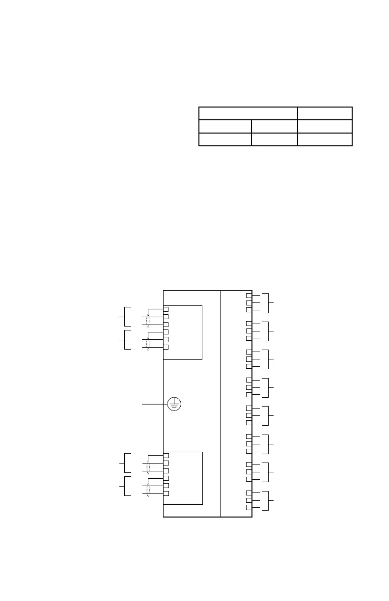
Figure 3-44— Relay Module Wiring Terminal Conguration
Controller Firmware S
³
Revision Version Version
A 2.01 2.0.8.0
COM Connector, Terminals 1 to 6
LON Terminals
Be sure to observe polarity when wiring the
LON.
1 — "A" side of signaling circuit for COM 1
2 — "B" side of signaling circuit for COM 1
4 — "A" side of signaling circuit for COM 2
5 — "B" side of signaling circuit for COM 2
3 & 6 — shield connections.
Channel Connectors, Terminals 1 to 24
Unsupervised Output Ancillary Applications
(Unrelated to Fire Detection/Protection)
Connect external wiring to the appropriate
terminals on the relay module terminal block.
See Figure 3-44.
CONFIGURATION
Setting Relay Module Network Address
One unique network address must be assigned
to each relay module. The address is set by
the 8 switch DIP assembly on the relay module.
The address is binary coded and is the sum
of all switches placed in the “closed” position.
Each discrete point of a relay module has
a tag number and a descriptor for unique
identification.
Det-Tronics S
³
Safety System Software is used
for device configuration. The following shows
the minimum software/firmware releases:
ANALOG INPUT MODULE
INSTALLATION
MOUNTING
The Analog Input Module must be properly
installed in a suitable enclosure that is rated
for the location. The enclosure must provide
space to install and wire the device and must
also provide for ground wire termination.
Access into the enclosure must be gained by
using a special tool to open the enclosure.