3-38
95-8533
18.2
For initiating device circuit(s) for use
with the deluge and pre-action system
conguration, an Enhanced Discrete Input/
Output Module (EDIO) must be used.
NOTE
In EQP systems with EQP2120PS(–B)
Power Supplies, the secondary power
is customer supplied and must be
accepted by the Authority Having
Jurisdiction (AHJ).
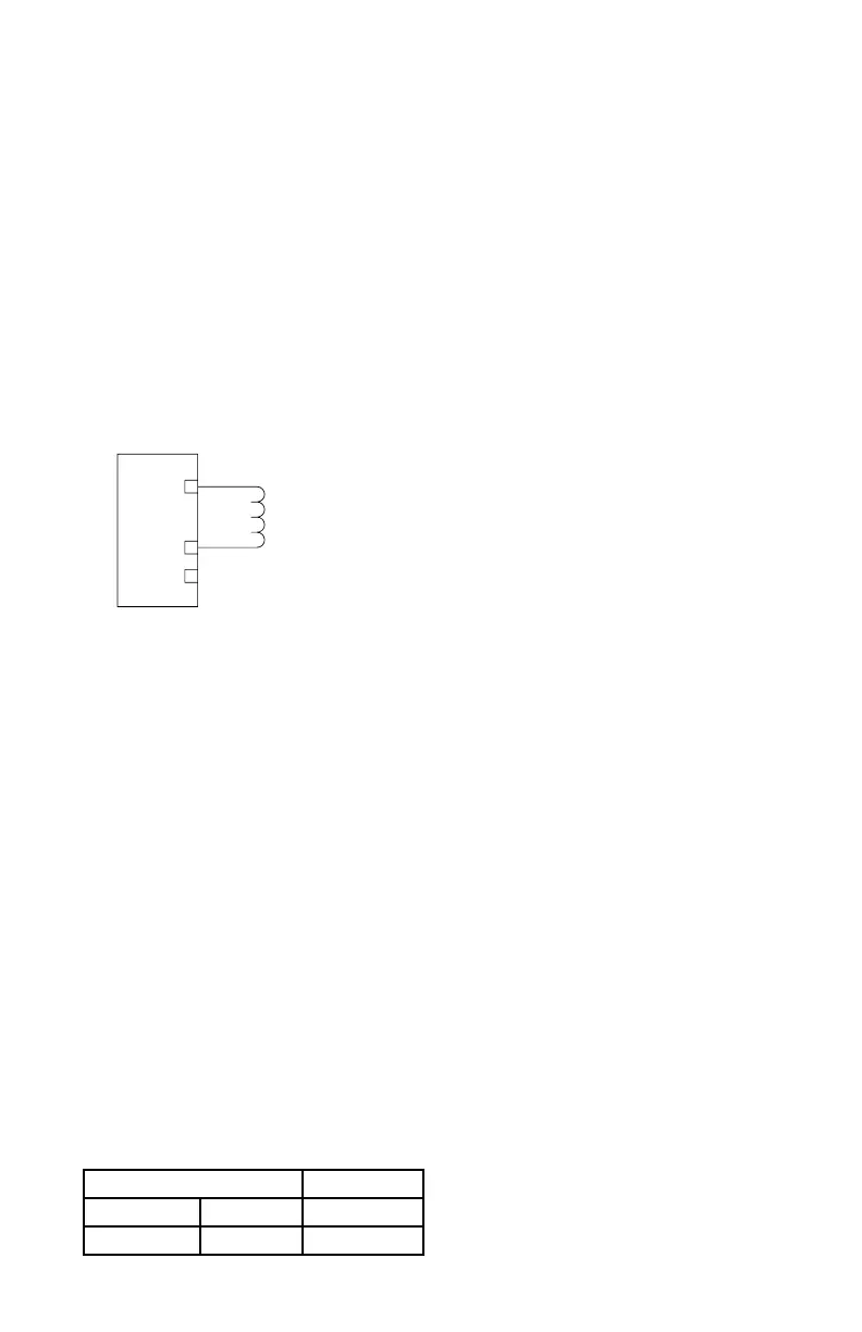
Unsupervised Output Ancillary
Applications (Unrelated to Fire Detection/
Protection)
Connect external wiring to the appropriate
terminals on the DCIO terminal block. See
Figure 3-43.
NOTE
No connection should be made to the “+
Supply” terminal.
CONFIGURATION
Setting DCIO Network Address
One unique network address must be assigned
to each DCIO module. The address is set
by the 8 switch DIP assembly on the DCIO
module. The address is binary coded and is
the sum of all switches placed in the “closed”
position.
Each discrete point of a DCIO module has
a tag number and a descriptor for unique
identification. A tag number must include
zone designation, which will be shown on the
controller's display when the point is in alarm.
Det-Tronics S
³
Safety System Software is used
for device configuration. The following shows
the minimum software/firmware releases:
8 CHANNEL RELAY MODULE
INSTALLATION
The following paragraphs describe how to
properly install and configure the 8 Channel
Relay Module.
MOUNTING
The Relay Module must be properly installed
in a suitable enclosure that is rated for the
location. The enclosure must provide space
to install and wire the relay module and must
also provide for ground wire termination.
Access into the enclosure is gained by using
a special tool to open the enclosure. The
enclosure should be rated for the temperature
range of the location plus the temperature rise
of all equipment installed inside the enclosure.
The enclosure must be rated for electrical
equipment that is going to be installed. The
device can be panel or DIN rail mounted.
NOTE
It is recommended to maintain a
minimum of four inches clearance
between the module and other
equipment to provide adequate room for
wiring and ventilation.
WIRING
All electrical connections are made to the field
wiring connectors furnished with the module.
See Figure 3-45 for terminal identification.
Power Connector, Terminals 1 to 6
24 Vdc Power Input
1 — +
2 — –
3 — Shield*
4 — +
5 — –
6 — Shield*
*Shields on power wires are optional unless
required by local codes.
Connect the module power supply to terminals
1 and 2. If additional terminals are required for
powering other devices, these devices should
be connected to terminals 4 and 5. Shields are
to be connected to terminals 3 and 6.
+ SUPPLY A
IN– / OUT+ B
COMMON C
1
2
3
NOTE: SHUNT/FLYBACK DIODES DO NOT NEED
TO BE INSTALLED ON THE FIELD DEVICE.
CIRCUIT PROTECTION IS PROVIDED
WITHIN THE DCIO.
A2323
Figure 3-43—Unsupervised Output Conguration
Controller Firmware S
³
Revision Version Version
A 1.03 2.0.2.0