95-8533
3-37
18.2
Each output channel is individually activated
for response pattern:
– continuous output
– 60 beats per minute
– 120 beats per minute
– temporal
– supervisory
– timed
– trouble.
Supervised Output for Automatic Release
Supervised Output for Open Circuits
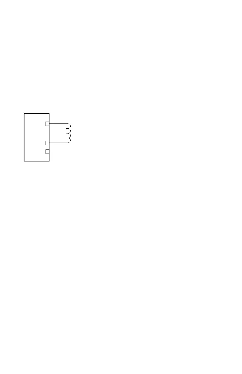
Connect external wiring to the appropriate
terminals on the DCIO terminal block. See
Figure 3-42.
Wire one or more releasing devices to the
module output.
NOTE
Make no connection to the “+ Supply”
terminal.
The output of the DCIO module supervises the
releasing circuit via the coil of the releasing
solenoid. It is essential to use a releasing device
approved for use with this output module.
NOTE
This type of output does not require
the use of EOL resistors or diodes to
supervise the circuit.
The output can be configured for latching,
continuous or timed response.
To ensure proper operating voltage, the maximum
wiring length from the power source to the DCIO
module must not exceed the values shown in
Table 3-10 for automatic release applications.
NOTE
For solenoids, this wire length includes
both the wiring from the power supply to
the DCIO module and the wiring from the
module to the solenoid.
Supervised Output for Deluge and
Pre-action
Connect external wiring to the appropriate
terminals on the DCIO terminal block. See
Figure 3-42.
The output of the DCIO module supervises the
releasing circuit via the coil of the releasing
solenoid. It is essential to use a releasing
device approved for use with this output
module.
NOTE
This type of output does not require
the use of EOL resistors or diodes to
supervise the circuit.
NOTE
For new or retrofit installations, any
manufacturer’s non-water based agent
release valves can be wired into the
outputs of the DCIO modules as long
as the devices utilize 24 Vdc and do not
exceed 2 amperes current draw.
NOTE
For FM system approval listing, pre-
action and deluge applications require
that only FM approved deluge valves
can be wired into the EDIO or DCIO
modules. Table 3-10 lists the supported
solenoid groups. Remember that the
valves must utilize 24 Vdc and must not
exceed 2 amperes current draw.
The output can be configured for latching,
continuous or timed response.
The maximum wiring length must not exceed
the values shown in Table 3-10 for deluge
and pre-action applications. Per FM Approval
requirements, the secondary power must
provide capacity for a 90 hour minimum
standby operation followed by a minimum of
10 minutes of releasing and alarm operation.
+ SUPPLY A
IN– / OUT+ B
COMMON C
1
2
3
NOTE: SHUNT/FLYBACK DIODES DO NOT NEED
TO BE INSTALLED ON THE FIELD DEVICE.
CIRCUIT PROTECTION IS PROVIDED
WITHIN THE DCIO.
A2323
Figure 3-42—Supervised Output Conguration
(Automatic Release)