4-8
95-8533
18.2
SEQUENCE OF EVENTS DURING A
CONFIGURATION DATA DOWNLOAD
During a configuration download, the controller
receives configuration data that is stored into
flash memory. During the download process,
the controller halts normal operation and
resets a number of controller functions. Items
affected and displayed during a configuration
data download are listed in the following steps:
1. Halt the static logic and user logic
programs.
2. Ignore field device LON communications.
However, the controller continues to
generate the LON heartbeat.
3. Silence the Controller’s audible
annunciator.
4. Initiate a Trouble condition that is signaled
by the amber Trouble LED and relay.
5. Clear all Alarm and Fault events.
6. De-energize all 8 Controller relays.
7. Ignore Modbus communication.
8. ControlNet communication continues.
EtherNet DLR communication goes
through reset and configuration. DLR
communication remains offline during this
sequence (approximately 30 seconds).
9. Text display’s first line indicates "***
Program Mode ***"
10. Text display’s third line displays download
status.
a) "Config Download" indicates the serial
transfer into memory from the PC to the
Controller.
b) "Erasing Flash" indicates that the
controller is electronically erasing the
contents of the Flash memory.
c)
"Writing to Flash" indicates that
configuration data stored in memory is
being written down into Flash memory.
d) "Flash Lock" indicates that the controller
is locking the configuration data into the
Flash memory.
CAUTION
The controller’s configuration data will
be corrupted if power is removed during
a download. Contact the factory if this
occurs.
11. Initialize the RS-485 and configuration
serial ports with new parameters.
12. Initialize the ControlNet or EtherNet DLR
option board with new parameters.
13. Enable static logic and user logic programs to
operate. The first scan program is run first.
14. Accept field device LON communications.
15. Poll the device type variable from LON field
devices.
16. Configure LON field devices.
17. Clear the Trouble condition.
18. Text display shows a normal operation
marquee message.
a) Text display’s first line indicates "Det-
Tronics Eagle Quantum Premier."
b) Text display’s third line displays time
(24 hour format) and date (month/day/
year).
NOTE
Depending on the condition of the LON
devices, faults may persist for a number
of minutes.
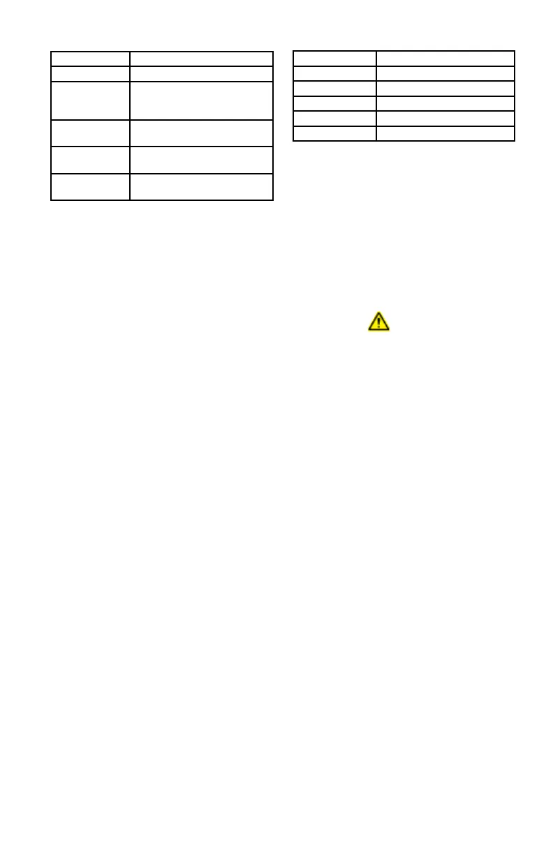
LED State Description
Off No link, no activity.
Green Link (100 Mbit/s) established.
Green, flickering Activity (100 Mbit/s)
Yellow Link (10 Mbit/s) established.
Yellow, flickering Activity (10 Mbit/s)
Table 4-6—EtherNet DLR Link Status 1 and Link Status 2 LEDs
LED State Description
Off No power or no IP address.
Green Online, one or more
connections established (CIP
Class 1 or 3).
Green, flashing Online, no connections
established.
Red Duplicate IP address, FATAL
error.
Red, flashing One or More connections
timed out (CIP Class 1 or 3).
Table 4-5—EtherNet DLR Network Status LED