3-48
95-8533
18.2
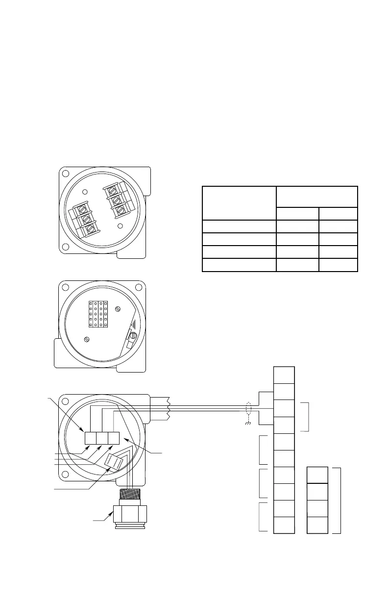
Alternate Method
If the transmitter board must be mounted
separate from the sensor (high temperature
applications, etc.), separate the sensor only,
leaving the transmitter PC board inside the
DCUEX enclosure. When using this installation
option, see Table 3-13 for maximum wiring
distances.
Mount the sensor directly to the separation kit
junction box. Use three conductor shielded
cable for the connection between the terminal
block in the separation kit junction box and P2
on the DCUEX transmitter board.
A plug with screw terminals is provided for
connecting the cable to P2 on the transmitter
board. Observe the wiring color code. Connect
the shield to the ground terminal in the DCUEX
junction box.
TYPICAL APPLICATIONS
Figure 3-57 is a simplified drawing of a
typical EQP system. This system includes an
EQP Controller, DCIO and various LON field
devices.
SENSOR
CATALYTIC SENSOR
ELECTROCHEMICAL SENSOR
TRANSMITTER BOARD
P1
P2
4 TO 20
–
+
C1878
POINTWATCH
GND
SPARE
CAL
4-20
RET
+24
CHASSIS
CAL
4-20
RET
+24
+
GRN
–
+
GRN
–
NOTE: ALWAYS ORIENT
JUNCTION BOX WITH
CATALYTIC SENSOR
POINTING DOWN.
1
2
3
4
5
6
7
8
9
10
DCU TERMINAL BOARD
14
13
12
11
–
–
+
+
24 VDC
COM 2
COM SHIELD
COM 1
POINTWATCH CALIBRATE
4 TO 20 MA IN
–
+
SENSOR POWER
A
B
B
A
SIG
–
+
Table 3-13—Maximum Separation Distances —
Combustible Gas Sensor to DCU (Alternate Method)
Wire Size
Maximum Separation
Distance
Feet Meters
18 AWG (1.0 mm
2
)* 40 12
16 AWG (1.5 mm
2
)* 60 18
14 AWG (2.5 mm
2
)* 100 30
12 AWG (4.0 mm
2
)* 150 45
*Approximate Metric Equivalent.
Figure 3-56—Sensor Separation Kits