95-8533
3-2
18.2
The Eagle Quantum Premier system utilizes a
power supply that provides an isolated 24 Vdc
battery backed-up power to the fire protection
devices as described in NFPA 72. More than
one power supply may be used in a system to
provide power to different sets of equipment as
part of the system.
The power supply wiring may consist of one or
more daisy-chained wire segments providing
power to the devices. For each of the daisy-
chained wire segments, the installer must
calculate the voltage drops that occur across
the devices in order to determine the gauge of
the wire that will be installed.
A power supply wiring diagram should contain
information describing wire distances and
current draws associated with all devices
connected to the wire segment. A typical
power supply wiring recommendation is that
the voltage drop from the power source to the
end device should not exceed 10%. Using 24
Vdc as a reference, the maximum voltage drop
should not exceed 2.4 Vdc. A wire gauge must
be selected to ensure that the end device has
at least 21.6 Vdc or higher.
In order to calculate the power supply voltage
for the end device, calculate the voltage drops
that occur due to each wire segment between
the devices. This involves determining the
total current draw and the two conductor wire
resistance per each wire segment.
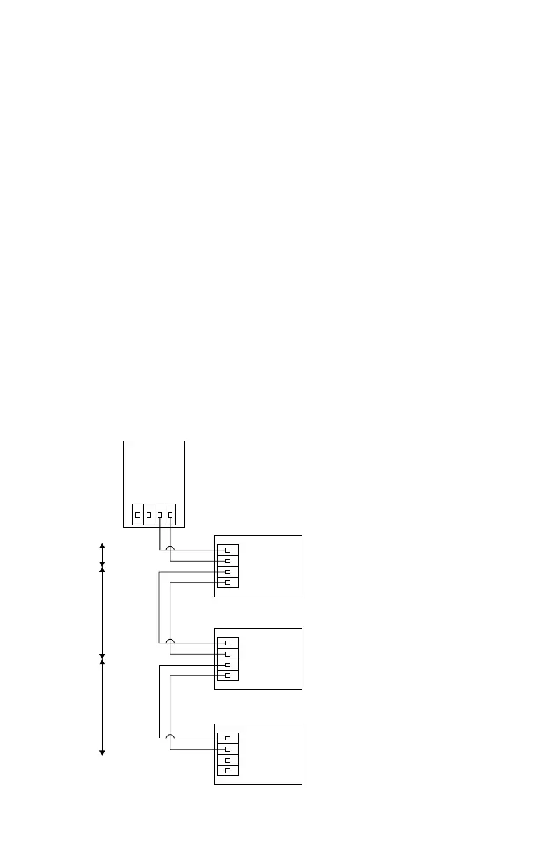
Example: Can 18 AWG wire be used to power
three devices from the 24 Vdc power supply?
Refer to the figure below for wiring and device
current draw information along with voltage
drop calculations.
Answer: If the Authority Having Jurisdiction
(AHJ) requires a voltage loss of 10% or less,
only 16 AWG wire could be used, since the end
device would require 21.4 Vdc. If there is no
local requirement, then 18 AWG wire could be
used to provide power to the devices.
Device 1
65 mA
Current Draw
Device 2
65 mA
Current Draw
Device 3
565 mA
Current Draw
24 vdc Power
Supply
18 AWG Single Wire Resistance: R = 0.6385 Ohms per 100 ft
2 Conductor Resistance: CR = 2 • R
Device 1 Voltage = Supply Voltage – (Voltage Drop)
= 24 – (I • CR)
= 24 – (0.695 • 0.6385)
= 23.55 vdc
Device 2 Voltage = Device 1 Voltage – (Voltage Drop)
= 23.55 – (I • CR)
= 23.55 – (0.630 • 1.9155)
= 22.35 vdc
Device 3 Voltage = Device 2 Voltage – (Voltage Drop)
= 22.35 – (I • CR)
= 22.35 – (0.565 • 1.9155)
= 21.27 vdc
50 ft
0.6385 Ohms
150 ft
1.9155 Ohms
150 ft
1.9155 Ohms
Total Current
695 mA
Total Current
630 mA
=
Device 2
+
Device 3
Total Current
565 mA
=
Device 3