95-8533
3-10
18.2
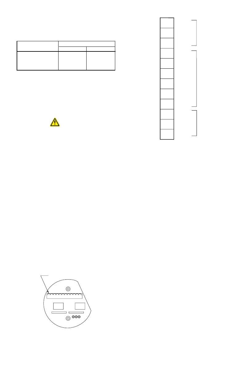
3. Connect shields to the designated "shield"
terminals. The two shield terminals are
connected internally to ensure shield
continuity.
CAUTION
Do not ground either shield at the
network extender enclosure. Insulate the
shields to prevent shorting to the device
housing or to any other conductor.
4. Check ALL wiring to ensure that proper
connections have been made.
5. Inspect the junction box O-ring to be sure
that it is in good condition.
6. Lubricate the O-ring and the threads of the
junction box cover with a thin coat of grease
to ease installation and ensure a watertight
enclosure.
NOTE
The recommended lubricant is a silicone
free grease, available from Det-Tronics.
7. Place the cover on the enclosure. Tighten
only until snug. Do not over tighten.
EQ3XXX CONTROLLER
INSTALLATION
The following paragraphs describe how to
properly install and configure the EQ3XXX
Controller.
ENCLOSURE REQUIREMENTS
The Controller must be properly installed in a
suitable enclosure that is rated for the location.
The enclosure must provide space to install
and wire the Controller and must also provide
for ground wire termination. The enclosure
must contain either a keyed lock or a special
tool to gain access into the enclosure. The
enclosure should be rated for the temperature
range of the location plus the temperature rise
of all equipment installed inside the enclosure.
The enclosure must be rated for electrical
equipment that is going to be installed.
112
A2021
Figure 3-2—Network Extender Wiring Terminal Location
Table 3-8—Maximum Wiring Length from Nominal 24 Vdc
Power Source to Network Extender
(Maximum wire lengths are based upon the cable’s physical
and electrical characteristics.)
*Approximate Metric Equivalent.
Wire Size
Maximum Wiring Distance
Feet Meters
18 AWG (1.0 mm
2
)* 2200 650
16 AWG (1.5 mm
2
)* 3500 750
14 AWG (2.5 mm
2
)* 5600 1700
1
2
3
4
5
6
7
8
9
10
A1947
11
12
SHIELD
SHIELD
SHIELD
SHIELD
A
B
A
B
–
+
–
+
COM 2
24 VDC
COM 1
Figure 3-3—Network Extender Wiring Terminal Identication