0.630
2.36
4.00
4.63
5.24
OPERATOR’S MANUAL
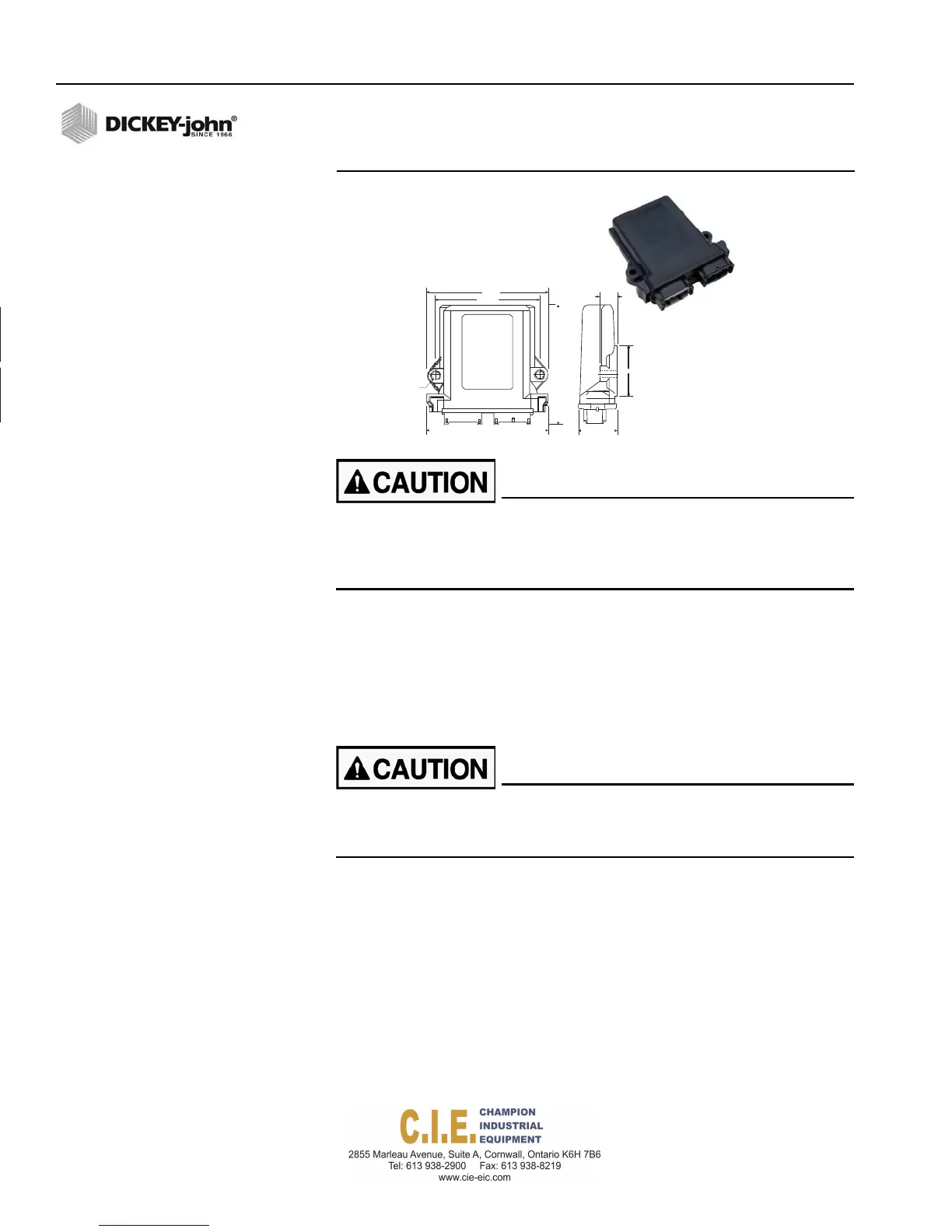
Figure 8
Output Module
.291
2 HOLES
4.68 1.37
Do not install the module in any orientation other than illustrated
in (Figure 7). The connection wires must not be mounted upward
as moisture can collect inside the unit and damage the circuits.
Ensure that module connectors do not face upward.
3.
Mount with the label side of the module facing out.
4.
To bolt the member to a frame:
–
Use the enclosure as a template to mark the location of the
mounting holes.
–
Drill two 9/32 inch diameter holes where marked.
–
Attach to frame using 1/4 x 20 bolts or other fastening devices as
illustrated in Figure 8.
Do not use the enclosure as a guide when drilling. Do not
overtighten nuts as this may damage the mounting tabs on the
enclosure.
12 / COMPONENT OVERVIEW
Flex4 Pro
TM
Control System
6010541 Rev A