7.45”
7.0”
6.80”
OPERATOR’S MANUAL
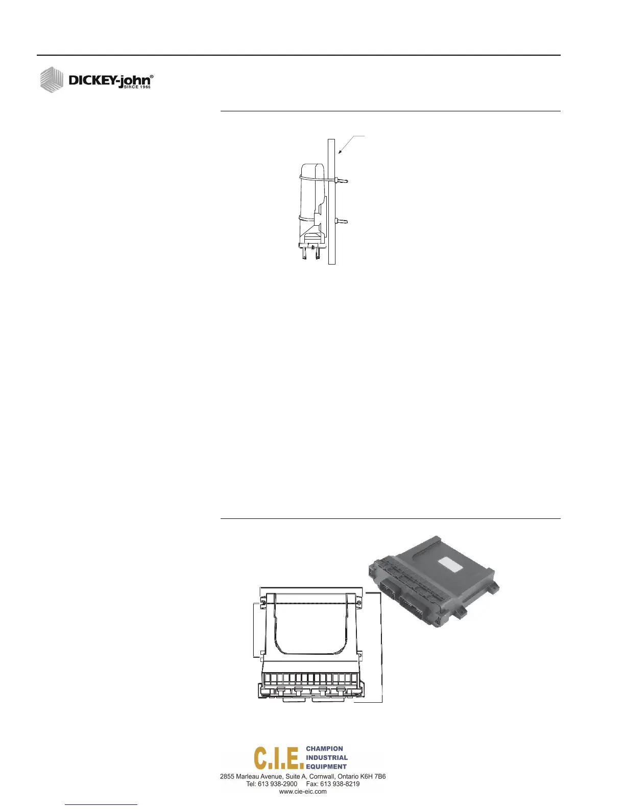
Figure 10
Securing Member with Tie Straps
TRUCK
FRAME
OR
BED
SUPPORT
6.
Connect an output module harness to the output module and connect
the output module harness to the Power/CAN backbone, refer to
(Figure 16).
7.
Connect each module harness to its module inserting both connectors
until the connector locking tabs engage.
8.
Lay out the boom shutoff harness along the boom frame to each of the
shutoff outputs.
9.
Route wires in locations where they will not be damaged.
10.
Secure the harness with tie straps.
NOTE: The last module harness in the
system must have a CAN
terminator installed for proper
system operation.
IMPORTANT: Ensure the locking tabs engage when inserting the
connectors. The connection is sealed only when the
locking tabs are fully engaged.
ATTACHING THE PCECU IN THE CAB
The PCECU module is the power management source for the Flex4 Pro
Control System. The PCECU mounts inside the cab and attaches to the cab
harness.
Figure 11
PCECU
3.93”
14 / COMPONENT OVERVIEW
Flex4 Pro
TM
Control System
6010541 Rev A