OPERATOR’S MANUAL
SYSTEM HARNESS CONNECTIONS
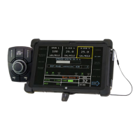
The Flex4 Pro
TM
control system connects to the truck cab harness and is
powered on and off when the ignition switch is powered on and off. The
Flex4 Pro tablet must be powered on after the ignition switch is powered on.
System harnessing connections include:
•
Cab harness
•
Rate control module harness
•
Optional output module harness
•
Optional extension harness
•
Optional electric motor/pump driver harness
•
Optional Road Watch adapter and Flex4 interface cable
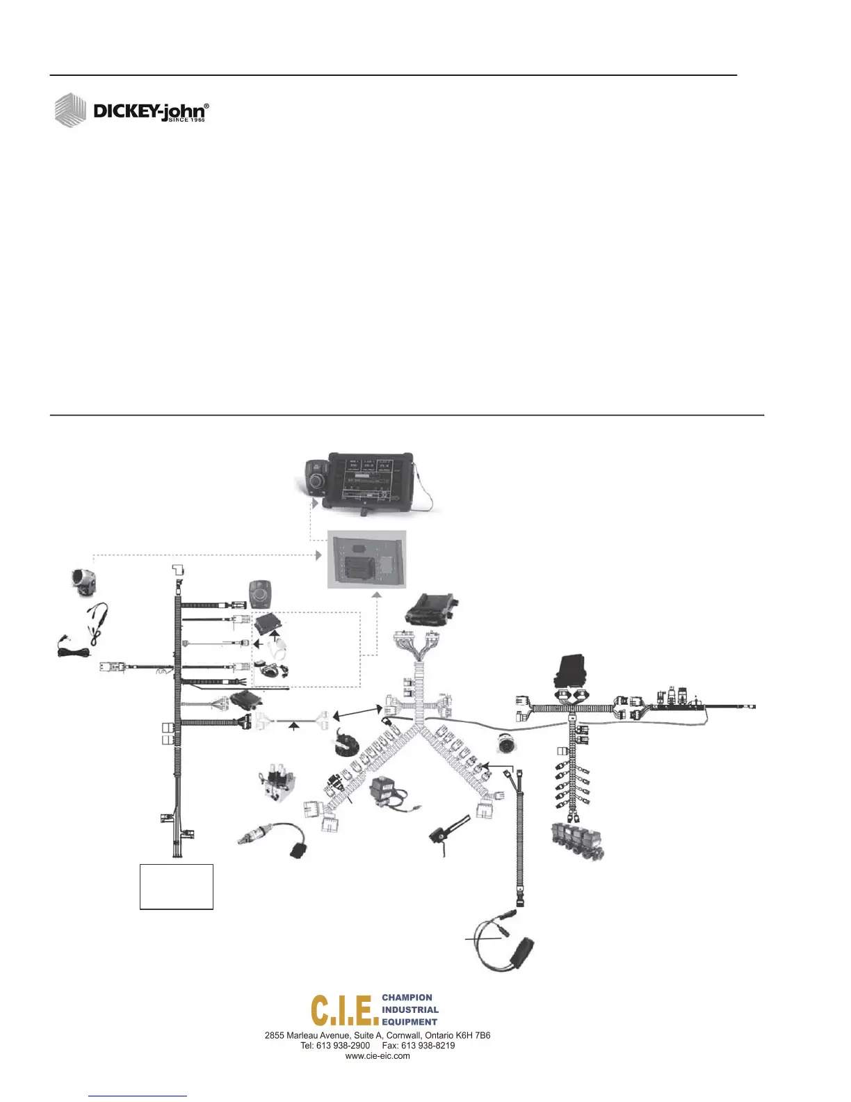
Figure 15
System Architecture with Electric Motor / Pump Driver and Optional Output Module Harness
power
adaptor
Camerato
AdaptorUSB
cable
Powerconnection
toVideoCamera
CAN
Terminator
Switch
Module
466495210
RAMToughHub
USBCanAdaptor
DCConverter
PCECU
Application
RateControlModule
467985410S1
RateControl
ModuleHarness
466495071
Flow
Output
module
466492101
connectsto
ElectricMotor/
PumpDriver
466495430
Harness
ExtensionHarness
466495060
Hydraulic
Valve
Down
Pressure
Rate
Ground
Speed
Control
Valve
Meter
GateHeight
Sensor
Flex4
Interface
Cable
466495072
Output
Module
Harness
466495081
Boom
Shutoff
Valve
RateControl
Moduleharness
Temperature
Sensor
Road
Watch
Adapter
20 / INSTALLATION
Flex4 Pro
TM
Control System
6010541 Rev A
Battery
Cab Power
6010766