OPERATOR’S MANUAL
CAB HARNESS
NOTE: The ignition lead must be
connected to switched +12VDC
for the system to power up and
down properly.
1.
Connect the power leads directly to the battery.
2.
Connect the ignition wire to a switched +12VDC.
3.
Connect the chassis ground lead to a direct battery ground connection.
4.
Connect the micro USB cable from the tablet charging port to the DC/
DC adapter USB plug.
5.
Connect the USB data cable to the mini USB port, upper right corner
labeled “USB IN” on the RAM tough hub.
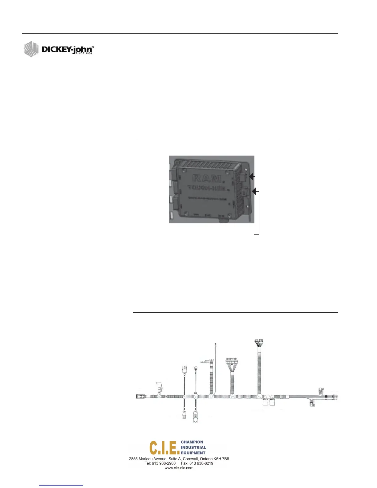
Figure 17
NOTE: Please see Appendix C for a
full cab harness connection
layout.
RAM Tough-HUB Connections
miniUSB
connection
Spade
connection
Connecttotabletusingbarreljack
connectorandthenplugUSBmaleinto
cablecomingoutoftheDC‐DCadapter
(femaleUSB)
6.
Connect the PCECU to the cab harness.
7.
Connect the CAN terminator, Operator Switch Module, and
RoadWatch to their respective connectors on the cab harness.
8.
For an installed camera, attach the 12V power camera adapter to the
harness. Plug the adapter into the USB tough hub mounted to the
accessories plate.
Figure 18
Cab Harness
22 / INSTALLATION
Flex4 Pro
TM
Control System
6010541 Rev A
Ignition
oExtensionHarness
orRateControl
ModuleHarness
Power
connection
tovideo
USBCAN
camera
Adapter
PCECU
CAN
Terminator
Switch
Module
to
battery
RAM
Mount
DC‐DC
Hub
Converter