OPERATOR’S MANUAL
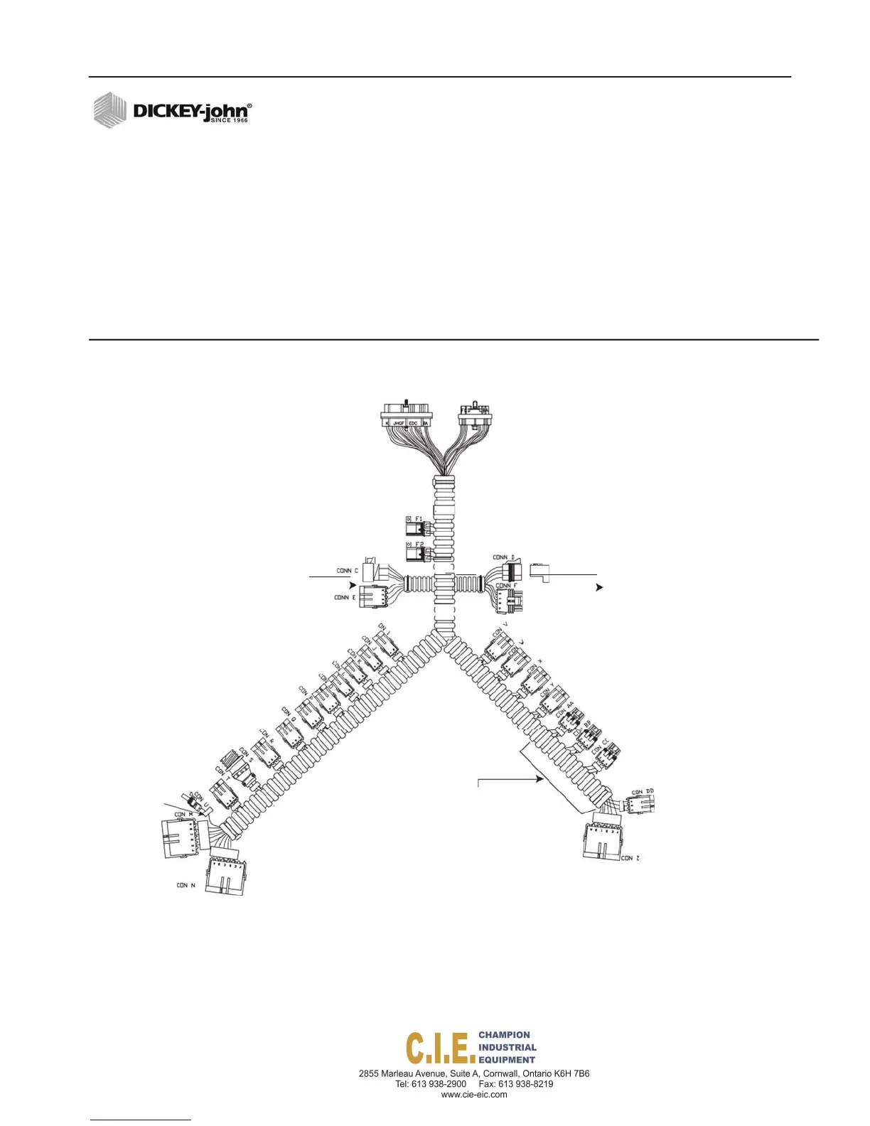
Figure 19
Rate Control Module Harness
RATE CONTROL MODULE HARNESS
1.
Connect the Rate Control Module harness to the mating connector of
the cab harness (use an extension harness if additional length is
needed).
2.
Secure harness as needed.
3.
Connect the module harness to the mating connectors of the CAN/
power backbone, if used. The Rate Control Module uses a 30 and
18-way connector with a jackscrew to secure the connector to the
module. The output module uses a pair of 12-pin connectors.
4.
Secure module harness as needed.
RateControl
Module
Cabor
Terminator
ElectricPump
Extension
DriverHarness,
Harness
PWMCh4AuxS/Spinner
PWMCh3Granular
PWMCh2Auxiliary
PWMCh1Liquid
CH4SpinnerFeedback
CH1LiquidFeedback
CH2Auxiliary Feedback
CH3GranularFeedback
GroundSpeed
RemoteOn/Off
Joystick
ExtensionHarness,
orOutput Module
Digital1Sensor
Harness
Digital2Sensor
HopperLevelSensor
RemoteBlast
Ch2Pressure/BedHeight(Analog1)
DownPressureSensor(Analog4)
GateHeightSensor(Analog3)
Flex4Interfacecable
Scraper
Servo1
Liquid
Servo2
Auxiliary
attachestoanyofthe
analog1‐4conn ectors.
RoadWatchTemperature
SensorAdapterconnectsto
theFlex4Interfacecable.
TankLevelSensor(Analog2)
BoomSection
Flex4 Pro
TM
Control System
6010541 Rev A
INSTALLATION / 23