Control|24 Guide14
Control|24 Back Panel
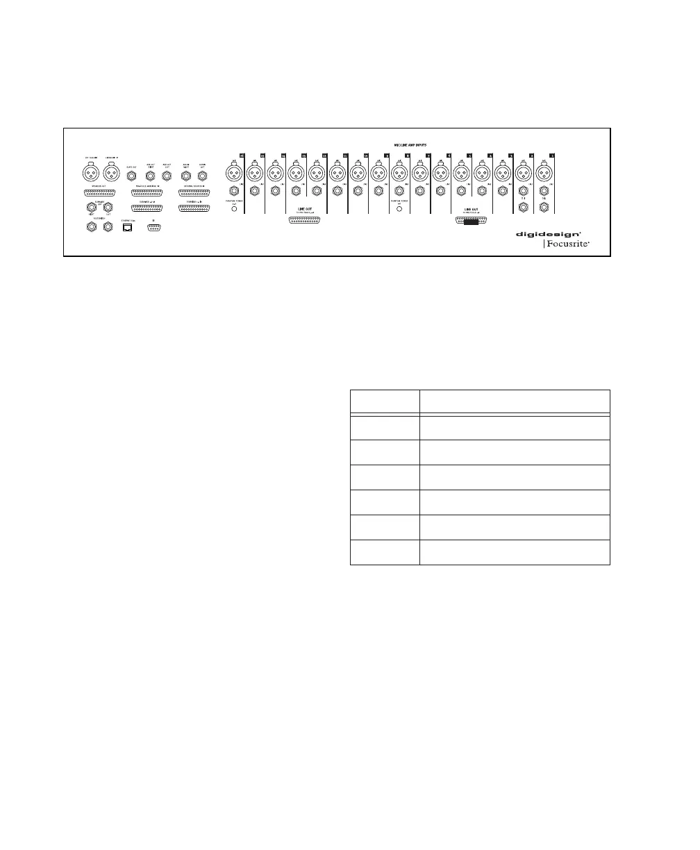
The Control|24 back panel provides the following connectors.
25-pin D-Sub Connectors
The 25-pin D-Sub connectors provide access to
the Contro|24 mic preamp outputs, and to most
monitoring and routing features.
Input
Four of the 25-pin D-Sub connectors provide in-
put to Control|24 for monitoring, mixing, and
submixing.
PRO TOOLS MONITOR IN Provide up to eight
channels of input to Control|24, to connect ste-
reo or multichannel Pro Tools outputs for mon-
itoring and mixing through Control|24.
These inputs should be connected directly to
the corresponding outputs on a Pro Tools audio
interface.
Figure 1. Back panel connectors and switches
PRO TOOLS MONITOR IN
Channel Signal
1
Pro Tools 1 Input (Left)
2
Pro Tools 2 Input (Right)
3
Pro Tools 3 Input (Center)
4
Pro Tools 4 Input (Sub)
5
Pro Tools 5 Input (Left Surround)
6
Pro Tools 6 Input (Right Surround)