EasyManua.ls Logo

Dobot M1 - Page 43

Dobot M1
140 pages
Print Icon
To Next Page IconTo Next Page
To Previous Page IconTo Previous Page
Loading...
Dobot M1 User Guide 5 Installation and Commissioning
Issue V1.3.4 (2019-05-23) User Guide Copyright © Yuejiang Technology Co., Ltd
40
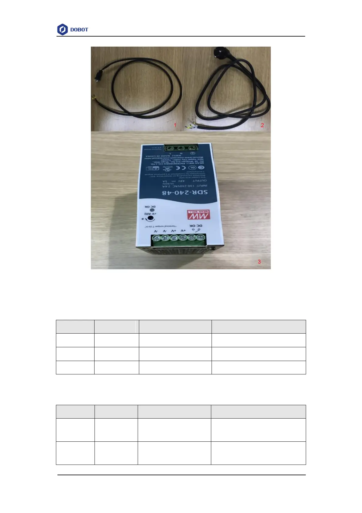
Figure 5.4 Power cables and power adapter
The input and output interfaces of the power adapter are shown in Table 5.1 and Table 5.2.
Table 5.1 The power adapter input interface description
No.
Name
Function
Voltage/Current
1
AC_L
L of the AC power
100V-240V AC/2.6A
2
AC_N
N of the AC power
100V-240V AC/2.6A
3
GND
GND
GND
Table 5.2 The power adapter output interface description
No.
Name
Function
Voltage/Current
1
V+
Positive electrode of the DC
power
48V DC/5A
2
V-
Negative electrode of the DC
power
GND/5A

Table of Contents

Other manuals for Dobot M1

Related product manuals