Thread cutter
Service Instructions 1767 - 00.0 - 12/2016 77
Important
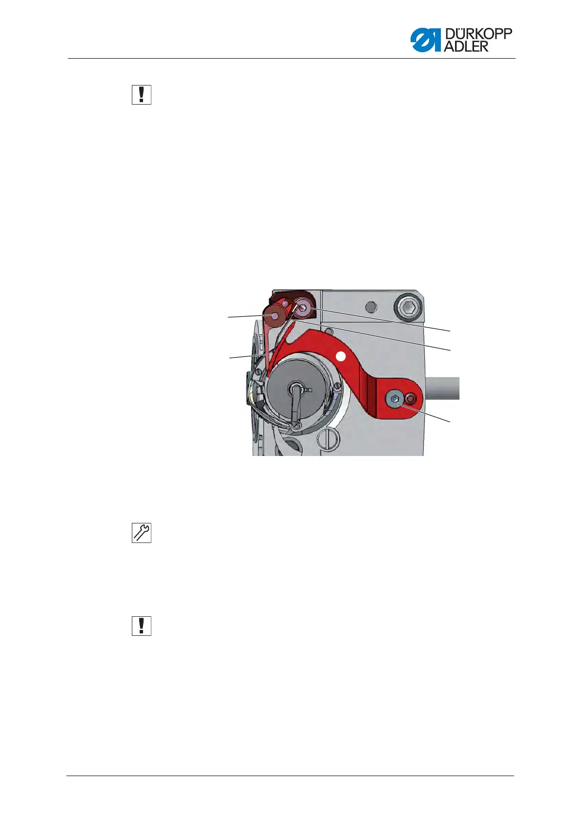
Tighten the 4 threaded pins (2) on the clamping ring (1) before you loosen
the threaded pins (5). The clamping ring (1) and control cam (4) are both
mutually used as a stop and should not be loosened at the same time.
4. Loosen the threaded pins (5).
5. Press the actuating lever (7) against the solenoid (9).
6. Turn the control cam (4) such that its widest extent (6) is at the top,
next to the roller (3).
7. Move the control cam (4) such that the distance between its widest
extent (6) and the roller (3) is 0.1 mm at most.
8. Tighten the threaded pins (5).
9. Loosen the clamping screw (8) on the actuating lever (7).
Fig. 62: Setting the cutoff curve (2)
10. Turn the thread-pulling knife (12) such that the circle mark is exactly
next to the tip of the counter blade (11).
11. Tighten the clamping screw (8) on the actuating lever (7) such that the
actuating lever (7) has no axial play.
12. Loosen all 4 threaded pins (2) on the clamping ring (1).
13. Push the clamping ring (1) to the right up against the control cam (4).
Important
Check the loop stroke position ( p. 54).
14. Tighten all 4 threaded pins (2) on the clamping ring (1).
(10) - Screw
(11) - Counter blade
(12) - Thread-pulling knife
(13) - Screw
(14) - Hook thread clamp
(15) - Screw
<
0
,
.
+
^
 Loading...