Programming
Service Instructions 867-M PREMIUM - 03.0 - 05/2017 121
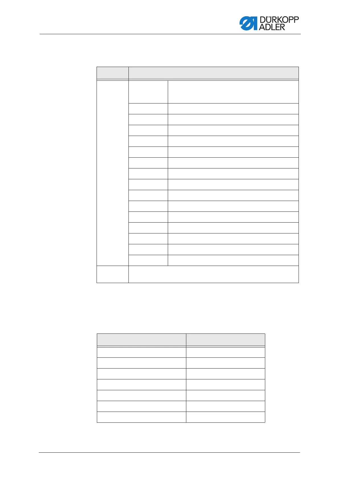
A mode can be allocated to every input (parameter T 53 00). The following
table lists the modes:
20.6.4 Setting the Output configuration (Output Config) parameter
Configure and allocate the outputs here. The table shows the outputs and
their allocation. The pins on the circuit board are labeled and must be allo-
cated according to the table, depending on what was connected to the pin.
Menu item Setting options
Mode 0, 7, 9, 10, 13,
14, 16, 17, 19,
22, 24
No function
1 Threading position
2 Bartack active/inactive.
3 Manual bartack
4 Half stitch
5 Full stitch
6 Point position
8 Needle height
11 2nd Needle thread tension
12 Change of stitch length
15 Seam center guide/puller
18 Light barrier
20 Operation lock when contact is opened normally (NO)
21 Quick stroke height adjustment
23 Change to next seam section
25 2nd Position of edge guide
Stored ON – stored
OFF – not stored
Machine output signal Output
ML (X22) X120B.9
NK (X22) X120B.10
RA (X16) X120B.12
STL (X17) X120B.22
STL(FA) (X18) X120B.23
FL (X15) (X22) X90.12
FF3 OUT (X22) X90.15

 Loading...