Thread cutter
70 Service Instructions 867-M PREMIUM - 03.0 - 05/2017
To set the height of the thread-pulling knife:
1. Open the throat plate slide ( p. 20)
2. Loosen the screw (5).
3. Remove the thread-pulling knife (2).
4. Place as many washers between thread-pulling knife (2) and knife
carrier (4) as necessary to ensure that the upper edges of the counter
blade (1) and thread-pulling knife (2) are at the same height.
5. Keep any unrequired washers on the top side between the thread-
pulling knife (2) and screw (5).
6. Tighten the thread-pulling knife (2) using the screw (5).
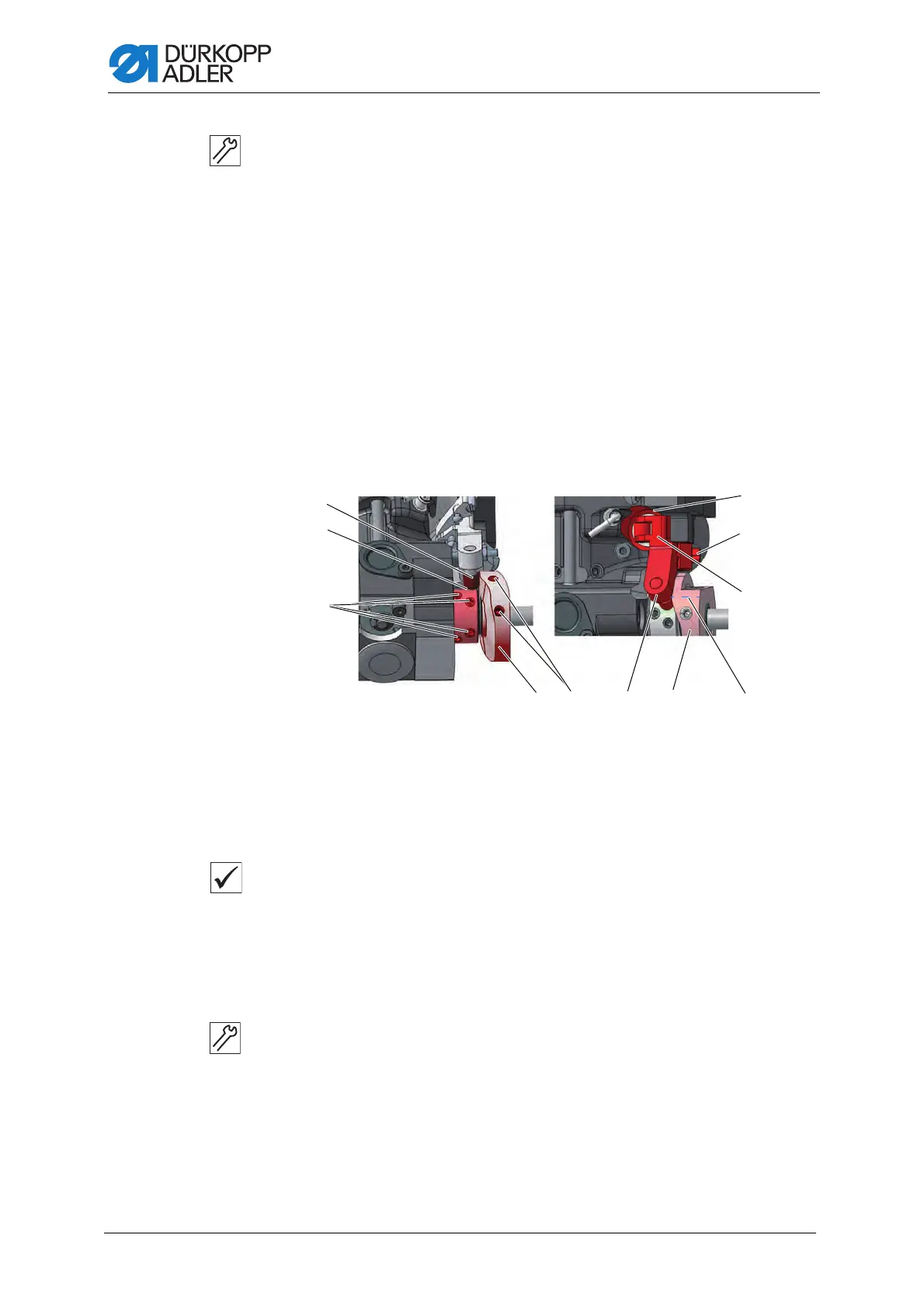
15.2 Setting the cutoff curve
Fig. 59: Setting the cutoff curve (1)
Proper setting
The control cam (4) makes direct contact with the clamping ring (2).
The distance between the widest extent (6) of the control cam (4) and the
roller (1) is 0.1 mm at most.
In resting position, the circle mark on the cutting edge of the thread-pulling
knife is exactly next to the tip of the counter blade.
To set the cutoff curve:
1. Tilt the machine head ( p. 16).
2. Open the throat plate slide ( p. 20)
3. Loosen the threaded pins (3) on the clamping ring (2).
4. Push the clamping ring (2) as far as it will go to the left.
5. Tighten the threaded pins (3) on the clamping ring (2).
(1) - Roller
(2) - Clamping ring
(3) - Threaded pins
(4) - Control cam
(5) - Threaded pins
(6) - Widest extent
(7) - Actuating lever
(8) - Clamping screw
(9) - Solenoid

 Loading...