Setting the mechanical stitch adjustment
Service Instructions 867-M PREMIUM - 03.0 - 05/2017 33
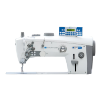
Fig. 21: Setting the mechanical stitch adjustment (2)
4. Insert the locking pin (9) into the hole (7) on the bearing bracket and
into the recess (8) in the control cam.
5. Manually position the plates (2) so that they are parallel.
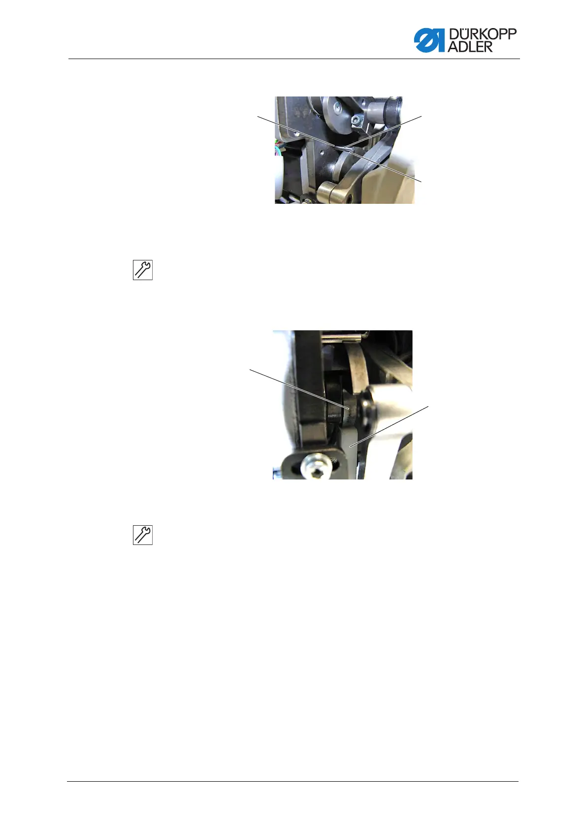
Fig. 22: Setting the mechanical stitch adjustment (3)
6. Set the lever (6) so that the white plastic track (11) abuts on the control
cam (10) without play.
7. Verify that the plates (2) are still parallel to one another.
8. Tighten the screw (5).
9. Attach the spring (4).
Next, pull the lever with the plastic track (11) through the spring of the
stitch regulator gear and into the stop of the control cam (10).
10. Check whether the plates are still parallel; if not, repeat the setting.
(7) - Hole
(8) - Recess
(9) - Locking pin ∅ 5mm
(10) - Control cam (11) - Plastic track

 Loading...