Position of the hook and needle
Service Instructions 867-M PREMIUM - 03.0 - 05/2017 47
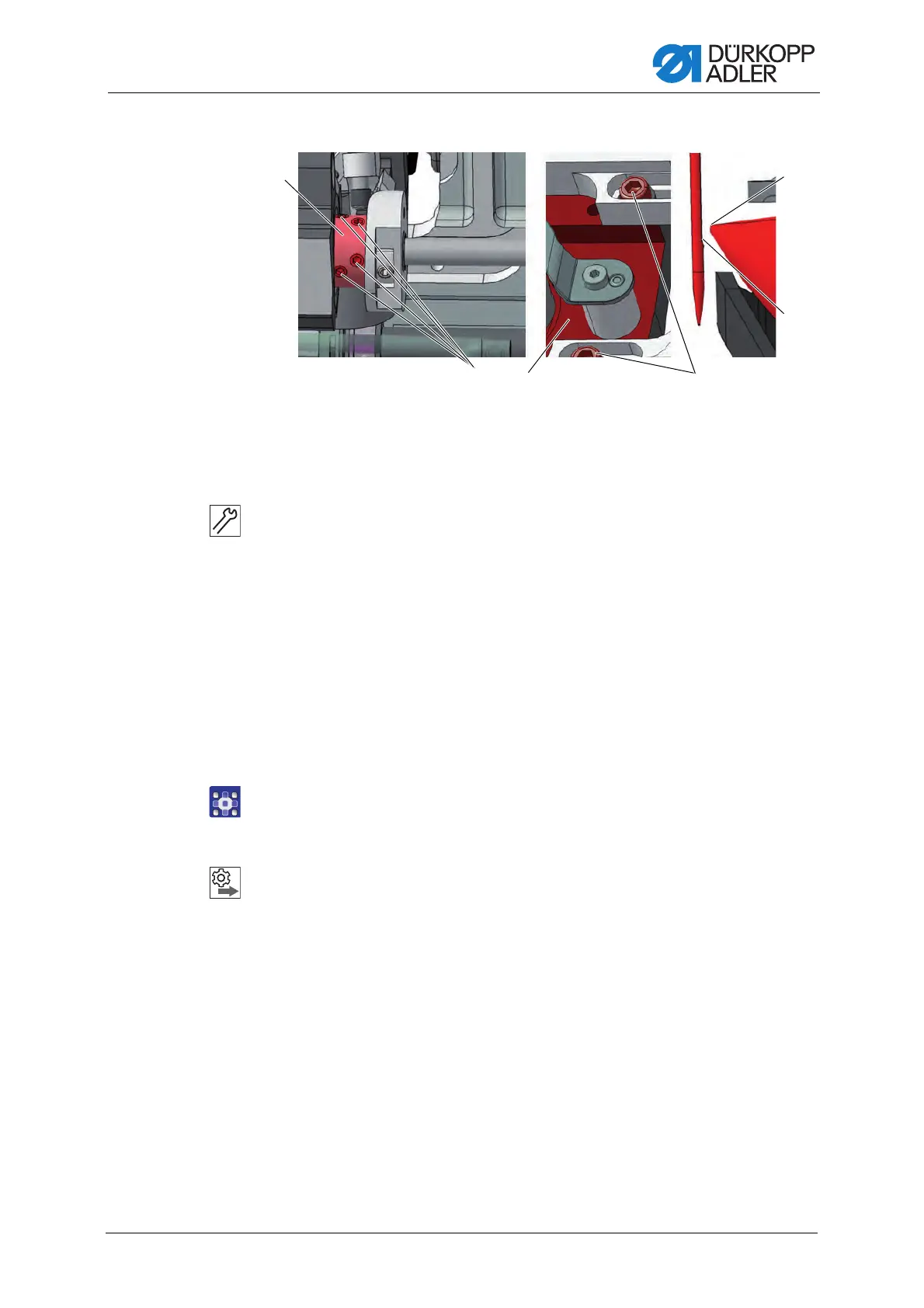
Fig. 34: Setting the hook side clearance
4. Lock the machine in place at position 1 ( p. 24).
5. Loosen the screws (4) for the hook support (3).
6. Loosen the threaded pins (2) for the hook clamping ring (1).
7. Shift the hook support (3) laterally.
The distance between the hook tip (6) and the groove of the
needle (5) is maximum 0.1 mm.
The hook tip (6) does not touch the needle.
8. Tighten the screws (4) for the hook support (3).
9. Check the loop stroke position ( p. 48).
10. Tighten the threaded pins (2) for the clamping ring (1).
11. Remove the lock.
12. Finish the service routine.
Order
Then, check the following settings:
• Position of the needle guard ( p. 50)
(1) - Clamping ring
(2) - Threaded pins
(3) - Hook support
(4) - Screws
(5) - Needle groove
(6) - Hook tip

 Loading...