F 8.1 9
F_8.1_01_GB.fm 9-20
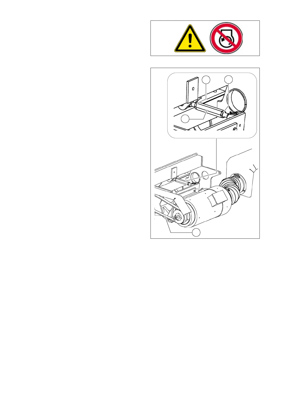
Drive belt (toothed belt)
Replacement of belt
- Unfasten both lock nuts (A) from the
clamping lock.
- Rotate and open clamping lock (B) un-
til belt (C) can be replaced.
A
Pre-tension newly fitted belt using
clamping lock (B).
- Checking / adjusting belt tension
Riemenspann.jpg
A
A
A
B
B