D 3.1 10
D_3.1_01_GB.fm 10-16
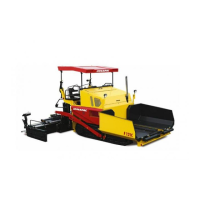
Ultrasonic auger limit switches (90)
(left and right)
A
The limit switches control the material
flow at the respective auger half.
The ultrasonic sensor is mounted by
means of an appropriate leverage to the
side plate. Loose clamping lever for ad-
justment and modify angle / height of the
sensor.
The cables must be connected to the re-
mote control units located at the sides of
the screed (socket (62)).
A
We recommend to adjust the limit switch
positions while the material is distributed.
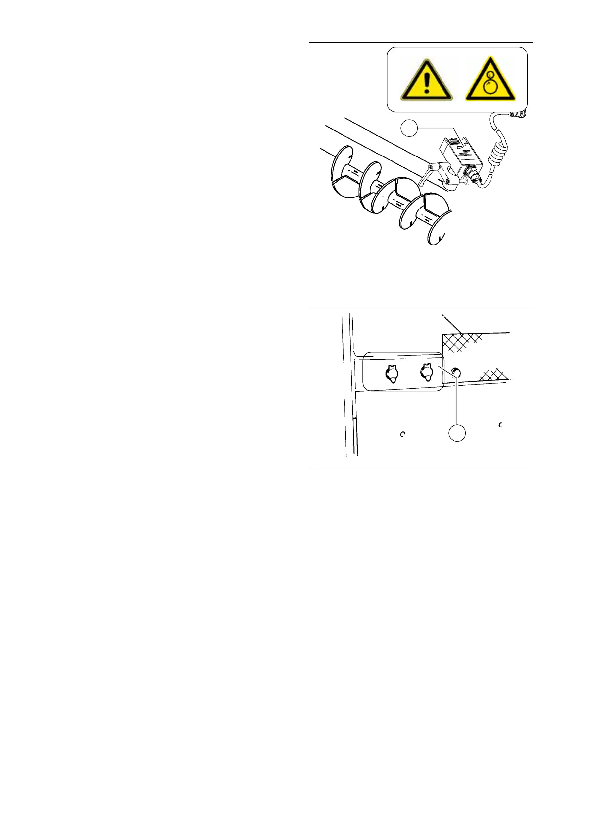
Sockets for working lights (left and
right) (92)
Connect the working lights (24 V) here.
- Power is present when the main
switch (72) is switched on.
A
As an option, one socket can be used to
provide power for an electrically heated
seat.
Ultra_Auger.bmp
90
F0124_A1.TIF
92