D 25
D F6C.GB 25-50 0504
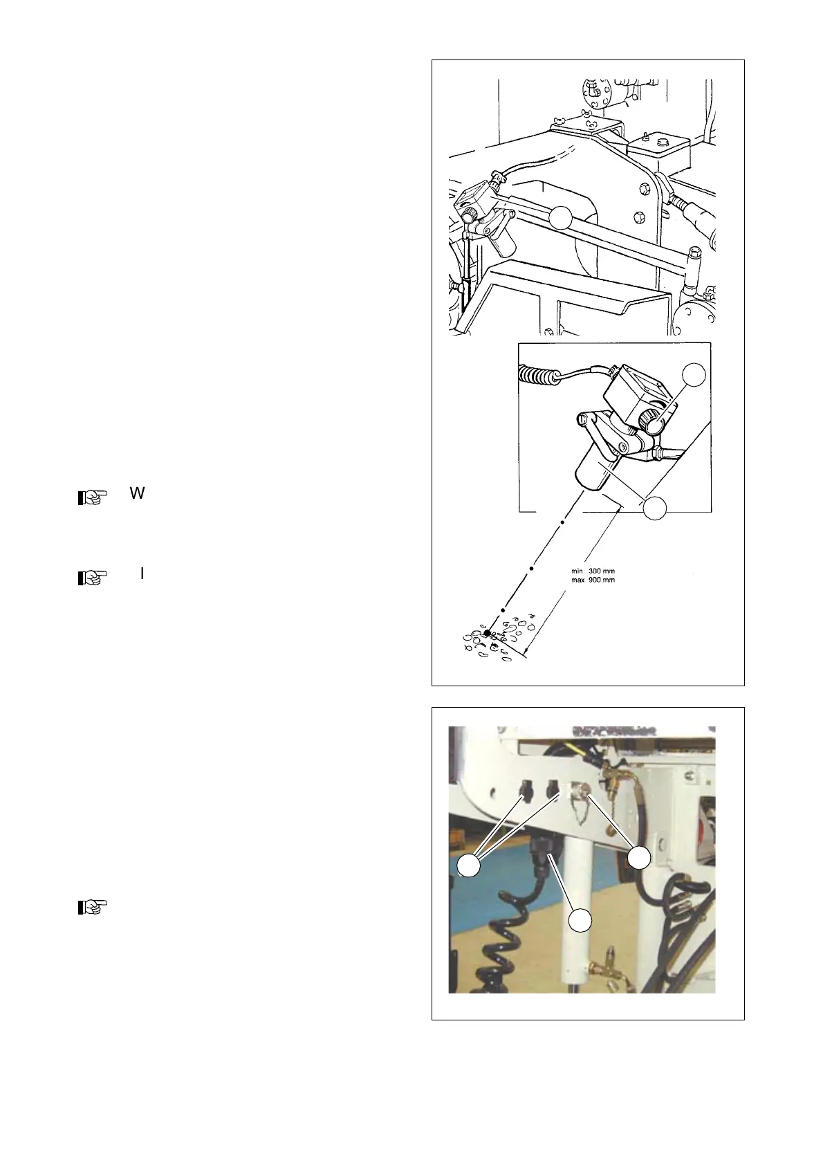
Ultrasonic auger limit switch (72)
On each side, the ultrasonic sensor (72)
is secured to the side shield using appro-
priate linkage.
The cables are connected to the remote
control units located at the sides of the
screed.
Setting the feed volume:
Align the sensor (72) towards the mixed
materials in front of the auger. The
sound waves should impact on the
mixed materials at right angles.
Adjust the deactivation point with the de-
sired material height by regulating the
potentiometer (A). The feed speed is au-
tomatically regulated depending on the
existing material height.
We recommend adjusting the limit
switch positions during material distribu-
tion.
Always keep sensors free of dirt.
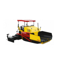
Sockets for working lights
(left and right) (73)
Two sockets are located on the rear con-
sole. Working lights (24 V) can be con-
nected here.
- Voltage is present when the main
switch (69) is switched on.
As an option, one socket can be used to
provide power for an electrically heated
seat, a rotating beacon or a separating
agent system.
Ultschall.tif
72
74
A
Steckdosen.jpg
73
74
75