EDR-3000 IM02602003E
Device Planning Parameters of the Device
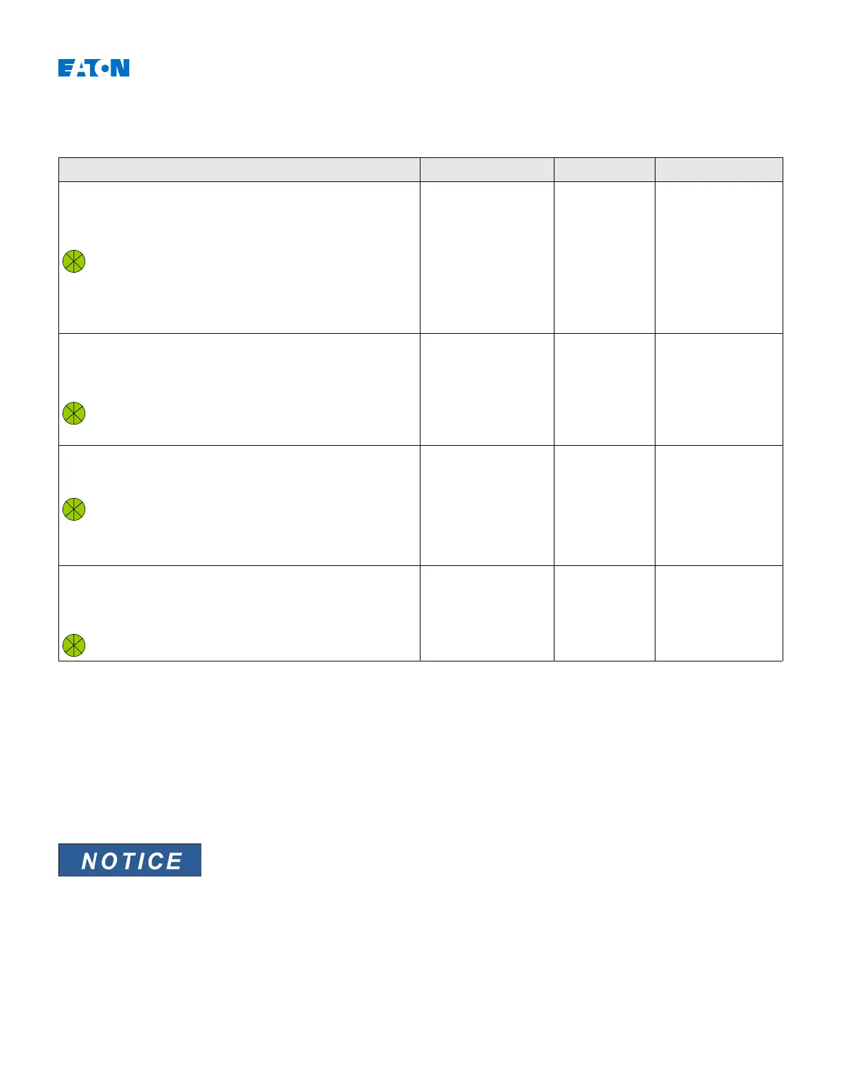
Parameter Description Options Default Menu path
Hardware Variant
1
Optional Hardware Extension »A« 4 Digital Inputs | 4
Relay Outputs,
»B« 8 Digital Inputs | 6
Relay Outputs | IRIG-B |
TCM,
»C« 4 Digital Inputs | 4
Relay Outputs | Zone
Interlocking | IRIG-B
4 Digital Inputs | 4
Relay Outputs
[EDR-3000]
Hardware Variant
2
Optional Hardware Extension »0« Phase Current
5A/1A, Ground Current
5A/1A,
»1« Phase Current
5A/1A, Sensitive Ground
Current 5A/1A
Phase Current
5A/1A, Ground
Current 5A/1A
[EDR-3000]
Communication Communication »B« RS 485: Modbus
RTU,
»H« Ethernet: IEC61850,
»I« RS 485 + Ethernet:
Modbus RTU + Modbus
TCP
»I« RS 485 +
Ethernet: Modbus
RTU + Modbus
TCP
[EDR-3000]
Printed Circuit
Board
Printed Circuit Board »A« Standard,
»B« Conformal Coating
»A« Standard [EDR-3000]
There are two mounts available for the EDR-3000: a Standard Mount and a Projection Mount. To order the EDR-3000
with a Standard Mount, append the device code with a zero (0). To order the EDR-3000 with a Projection Mount, ap-
pend the device code with a one (1). Refer to the table above details of the available device options.
A retrofit kit for Eaton IQ cutouts is available (Style No. 66D2217G01 – Catalog No. ER-IQEDRKIT). This kit is required
when replacing a DT-3000 with the EDR-3000.
The different variants (EDR-3000AXXX,EDR-3000BXXX,EDR-3000CXXX)
have different default-settings.
The manual contains only the default setting of one variant (EDR-3000A0BA).
www.eaton.com 23

 Loading...


