EDR-3000 IM02602003E
Overview of Slots - Assembly Groups
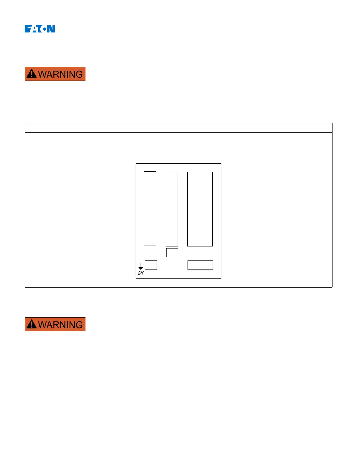
In line with the customers' requirement, the devices are combined in a
modular way (in compliance with the order code). In each of the slots, an
assembly/group may be integrated. In the following diagram, the terminal
assignment of the individual assembly/groups are shown. The exact
installation/placement of the individual modules can be determined from
the connection diagram attached to the top of your device.
Overview of Slots
Housing B1
Schematic Diagram
The housing must be carefully grounded. Connect a ground cable (4 to 6
mm
2
[AWG 12-10] / 1.7 Nm [15 In-lb]) to the housing, using the screw that is
marked with the ground symbol (at the rear side of the device).
The power supply card needs a separate ground connection (2.5 mm
2
[AWG 14] / 0.56-0.79 Nm [5-7 In-lb]) at terminal X1.
www.eaton.com 27
X1
X2 X3
Slot1 Slot2 Slot3
X100
X101
X103

 Loading...


