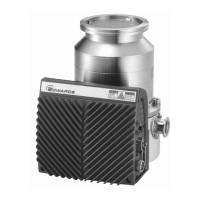
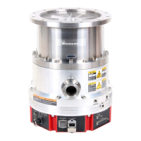
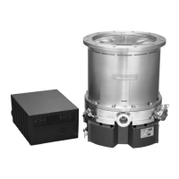
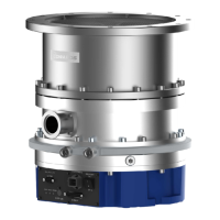
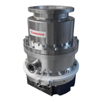
STP-iX457/iXU457 Series Turbomolecular Pump
MT-86E-001-F
Page
60
4
OPERATION
Pin Description
Pins for inputting the START signal.
Short the circuits between (1)-(6).
When the pins (1)-(6) are opened, the STP pump will stop.
Pins for inputting multiple functions signal.
One of the following functions is available by changing the
setting via the serial port. (refer to Section 5, “SERIAL
COMMUNICATION PROTOCOL” in this Instruction Manual, or
the Instruction Manual for the STP-Link [optional accessory])
1. Type A (Default)
They are set as pins for inputting the RESET signal in the
default state.
When a safety function operates, remove the cause of the
abnormality/error after confirming the STP pump has
stopped. When the cause of the abnormality/error is
removed, short the circuits between (11)-(6) for 0.3
seconds or more to reset the failure signal ("STATUS" LED
will change from red flash to green flash).
2. Type B
When the start signal input pins (1)-(6) are opened, they
function as the reset signal input pin. When the pins are
closed, they function as the second speed signal input pin.
When using the second speed function, set "ENABLE" by
the serial communication or the STP-Link.
When pins (11)-(6) are set to close, rotational speed will be
second speed when pump state is NORMAL.
When pins (11)-(6) are set to open, rotational speed will be
normal speed when pump state is NORMAL.
When using the second speed function to switch the
rotational speed through the serial communication port or
STP-Link, open the circuits between (11)-(6).
Table 14 - X2 REMOTE input signal pins
(1) (6)
START IN IN COM
(11) (6)
PROG IN IN COM

 Loading...
