STP-iX457/iXU457 Series Turbomolecular Pump
MT-86E-001-F
Page
66
4
OPERATION
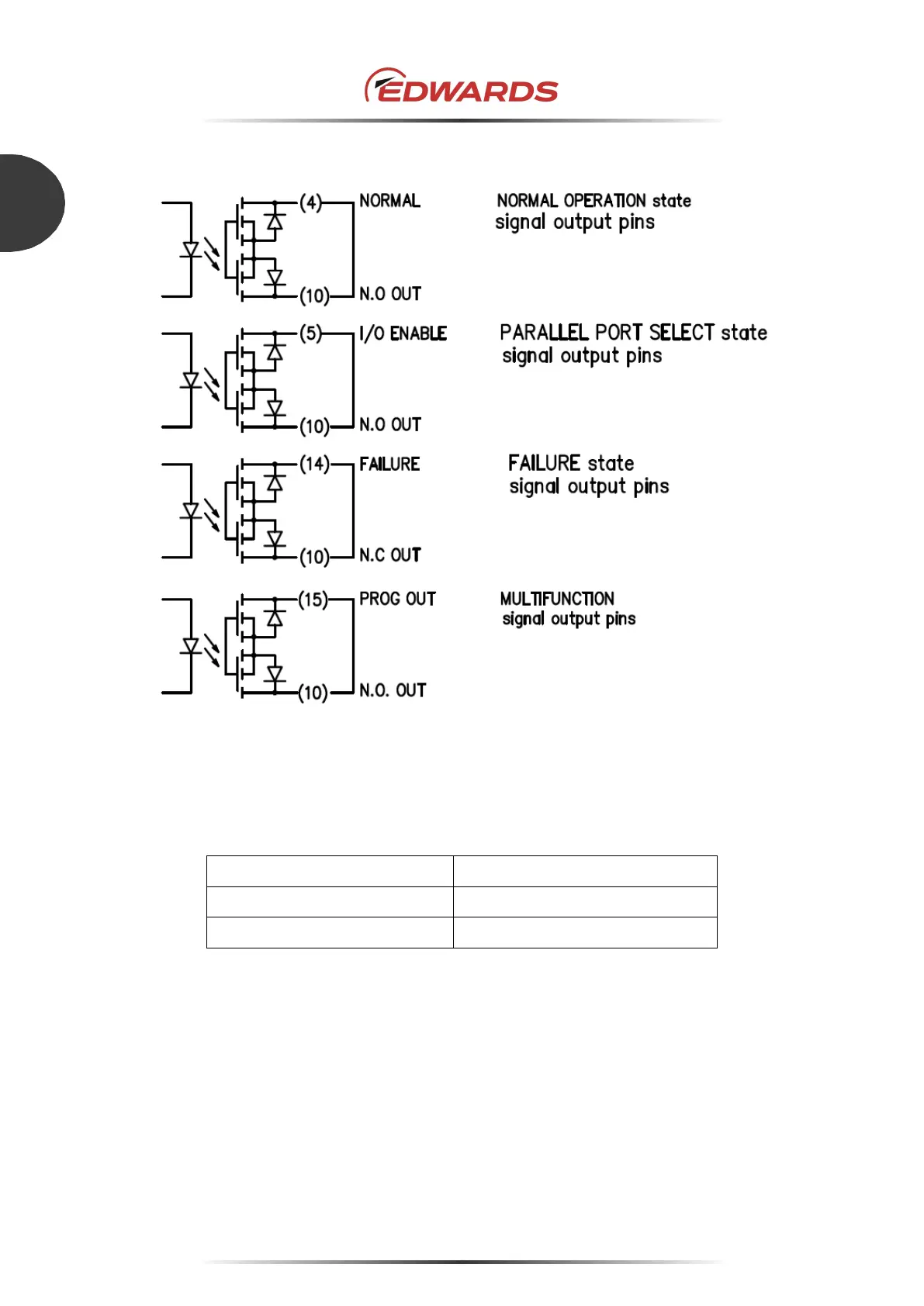
Figure 43 - X2 REMOTE output signal pins
Table 18 shows the rated contacts for four photo relays in Figure 43.
Resistance Load (COS Ø=1)
Maximum voltage 30 V DC
Maximum rated current 0.1 A
Table 18 - Rated contacts for four photo relays
 Loading...