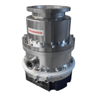
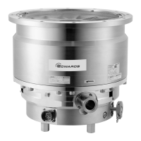
STP-iX457/iXU457 Series Turbomolecular Pump
MT-86E-001-F
Page
65
4
Pin Description
Pins for outputting multiple functions signal.
One of the following functions is available by changing the
setting via the serial port. (refer to Section 5, “SERIAL
COMMUNICATION PROTOCOL” in this Instruction Manual, or
the Instruction Manual for the STP-Link [optional accessory])
1. Type A (Default)
They are set as pins for outputting the pump operation
signal in the default state. These pins are closed when the
STP pump is in operation (acceleration, deceleration,
normal operation).
2. Type B
ACCELERATION state signal output
These pins are closed when the STP pump is in
acceleration.
3. Type C
BRAKE state signal output
These pins are closed when the STP pump is in brake.
4. Type D
FAILURE signal output N.O (FAIL N.O.)
When an abnormality/error is detected, the pins are
closed.
5. Type E
WARNING signal output
These pins are closed when the STP pump is WARNING
state.
6. Type F
LEVITATION state signal output
These pins are closed when the STP pump isn’t in
operation (acceleration, deceleration, normal operation).
7. Type G
*
ACCELERATION or BRAKE state signal output
(ACCEL./BRAKE)
These pins are closed when the STP pump is in
acceleration or brake.
Table 17 - X2 REMOTE output signal pins (continued)
*
Valid setting in software version 1.2 or later.
(15) (10)
PROG OUT
N.O. OUT
PROG OUT OUT COM

 Loading...
