126
Thedrawercoverhasthemembraneanduser
interfaceboardmountedinthecenterfrontsection
oftheplasticframe.Theframeonthebottomside
alsoholdstherollertrackthatthedraweritselfwill
sitintoallowittobeafullpulldrawer.
Thepowertooperatethedrawerandawirefrom
thefoodcompartmentlightswitchwillconnect
tothecontrolunitviaawireharnesscomingup
fromthebottomthroughtheserviceopeningfor
thewaterlinesandmid-levellightingwires.This
harnesswillconnecttothefourpinconnectorinthe
bottomrightbacksectionofthecontrolunit.(See
Figure5.)
Thewiringharnesscomingfromtheuserinterface
controlinthecoverwillconnecttoa10pin
connectorlocatedinthetoprightside,towardthe
frontofthecontrolunit.(SeeFigure5.)
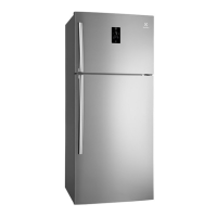
Thedrawercovercontainstheuserinterface
board,membranekeypad,theNTCthermistor
thatsensesthedrawertemperature,andthewiring
harnessthatrunsbetweentheuserInterfaceand
themaincontrolunit.(SeeFigure6.)
Addendum A - Perfect Temperature Drawer
Figure 5
115VPowerSupply4PinConnectorisinthislocation
onback.
10PinConnectorForUserInterfaceBoardWiring
HarnessComingFromCover
CAUTION
Ground yourself to the refrigerator cabinet
before dissembling any electronic parts.
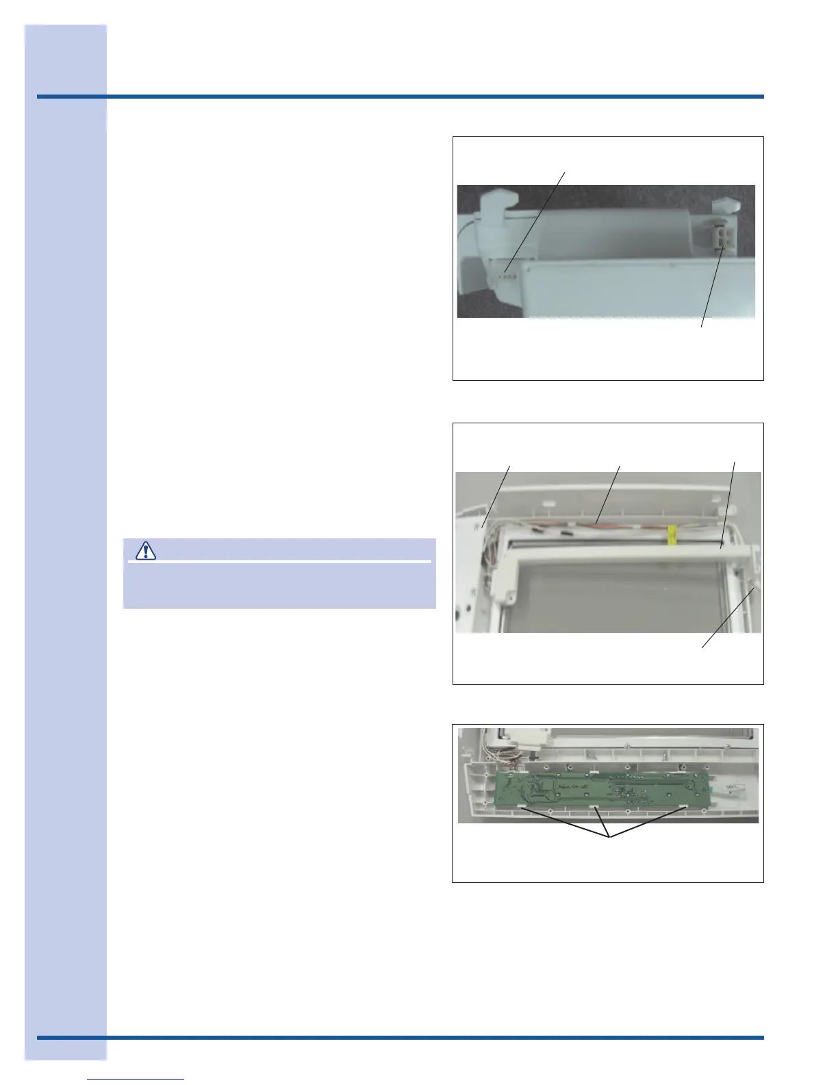
To service the user Interface board and touch
control: (SeeFigure7.)
1. Removethedrawer.
2. Reachbehindthecoverontherightsideand
releasetheconnectorplugfromthecover
harnesstothemaincontrolunit.
3. Liftthecoveroffthesupportsinthelinerand
pullitforward.
4 Removethecoverfrominsidetherefrigerator
andturnitoveronacleanatsurface.
5. Removethescrewsholdingtheuser
Interfaceboardcoverinplaceandremove
cover.
6. Theboardwillnowsnapoutoftheretainer.
7. Disconnectthemembranekeypadand
harnessconnectorribboncablefromthe
printedcircuitboardassembly.Pushbackon
thetabsalongthefrontedgeoftheboard
andlifttheuserInterfaceboardup,pullthe
boardoutfromundertherearretainersand
liftitoutofthecover.
Figure 6
CoverOver
InterfaceBoard
CoverOver
WiringHarness
ConnectorandHarnesstoControlUnit
Wiring
Harness
Figure 7
User Interface
Pushbackonthetabsalongthefrontedgeoftheboard.