85
Section F - Ice Maker
Thesolenoidcoildraws10to20wattsofpower.
Thecoiliswiredinserieswiththemoldheater,
acrossthesupplyvoltage.
Thermostat (Figure F6)
Thethermostatisasingle-pole,singlethrow
(SPST),bimetallic,disk-type,thermalswitch.It
automaticallystartstheharvestcyclewhentheice
isfrozen.Thethermostatclosesatatemperature
of9°F±2°.Wiredinserieswiththemoldheater,
thethermostatactsasasafetydeviceagainst
overheatingintheeventofmechanicalfailure.
Athermalmasticbondisprovidedwherethe
thermostatismountedagainstthemold.Agasket
preventswaterfromleakingintothesupport
housing.
Sensing Arm & Linkage (Figure F5 &
F6)
Thesensingarmiscam-drivenandoperatesa
switchthatcontrolsthequantityoficeproduced.In
theharvestCycle,thearmisraisedandlowered
duringeachofthetworevolutionsofthetiming
cam.Ifthesensingarmcomestorestontop
oficeinthestoragecompartmentduringeither
revolution,theswitchwillremainopenandstop
theicemakerattheendofthatrevolution.When
sufcienticeisremovedfromthestoragecontainer,
thesensingarmlowersandiceproduction
resumes.Tomanuallystoptheicemakerturnthe
switchlocatedonthehousingattheleftendofthe
icemakertooff.Operationisresumedwhenthe
switchisturnedbacktoon.
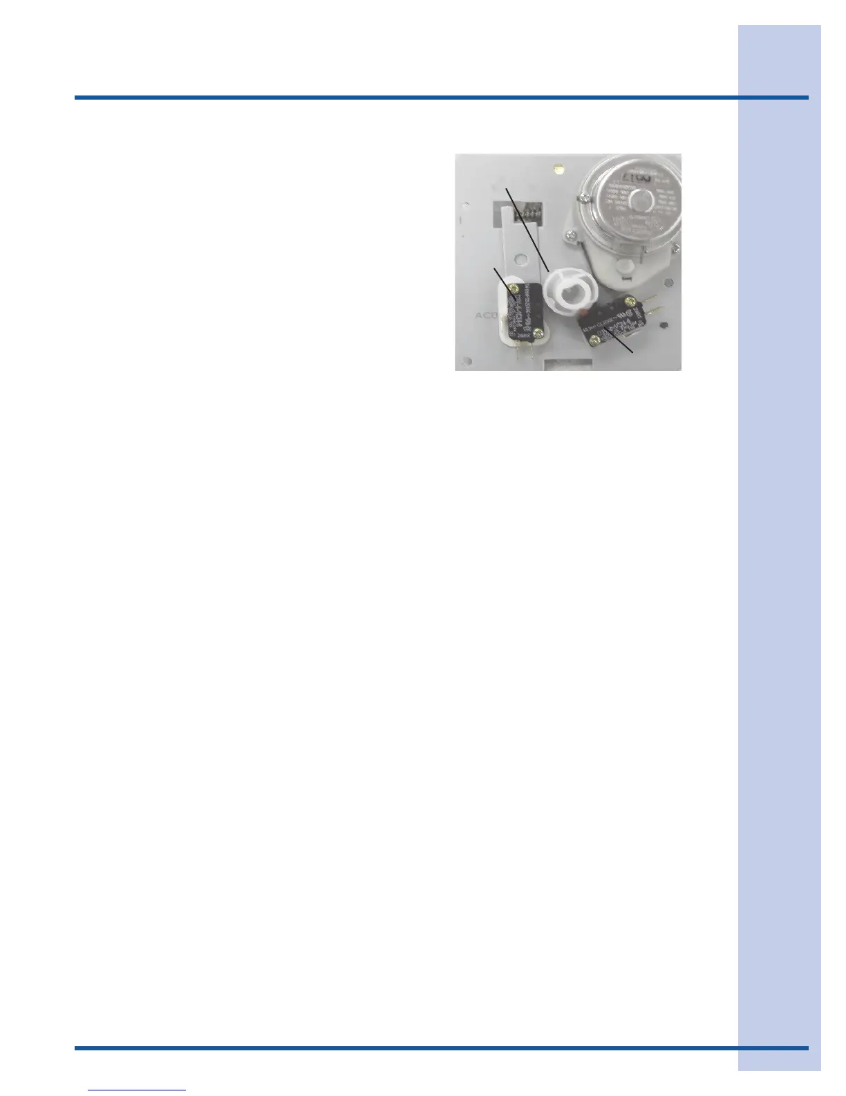
Timing Switches (See Figure F2)
Thethreetimingswitchesusedaresingle-pole,
doublethrow(SPDT).Theyareidenticalexceptfor
function,andcanbeusedinterchangeably.
1. Hold Switch-assurescompletionofa
revolutiononcetheicemakeroperationhas
started.
2. Water Fill Switch-opensthewatervalve
duringthellcycle.Itistheonlyadjustable
componentintheicemaker.
3. Shut-Off Switch-stopsicemakeroperation
whenthestoragecontainerisfullofIce.The
switchisopenedafterthesensingarmis
raisedtoitsmostuprightposition.Theswitch
ismountedtothetoprightwalloftheice
makersupport.(NotshowninFigureF6)
Figure F2
Motor
Timing Cam
Hold
Switch
Water Fill
Switch
Mounting Plate Back View
Thermal Cut-Out (TCO)
Thethermalcut-outisaone-timelimitfuseused
asasafetydevice.Itislocatedunderthemounting
plate,intheheadoftheicemaker,betweenthe
thermostatandwireconnector.
Ifthethermalcut-outopens,thecauseoffailure
mustbedeterminedandcorrectedpriorto
replacingtheTCO.NormalscausesoftheTCO
failingareabadthermostatorashortedcoilonthe
watervalve.
Timing Cam & Coupler
Threeseparatecamsarecombinedinonemolded
Delrinpart:
1. Innercamoperatesshut-offswitchleverarm.
2. Centercamoperatesholdswitch.
3. Outercamoperateswaterllswitch.
Onecamendisattachedtoalargetiminggear.
Theothercamendiscoupledtotheejector.
Timing Gear (Figure F1)
Thislargemoldedplasticgearisdrivenbythe
motorand,inturn,rotatesthecamandejector.
A“D”shapedholeinthegeartsoverthetiming
camhub.Spacertabsonthebacksideofthegear
preventthegearfrombindingonthemounting
plate.
Motor (Figure F2)
Alowwattage,stall-typemotordrivesthetiming
gear.Thisgearturnsthetimingcamandejector
bladesapproximatelyonerevolutioneverythree
minute(1/3RPM).