29
Reference Manual
00809-0100-2460, Rev DE
Installation
October 2018
Installation
3.5.5 Cabling for the TRL2/RS485 bus
In a Rosemount Tank Gauging system a Rosemount 2460 System Hub communicates with a TankMaster
control room PC using the TRL2/RS485 Modbus
™
protocol, see Section 2: Overview.
TRL2 bus
The TRL2 bus requires twisted and shielded pair wiring with a minimum cross-sectional area of 0.50 mm
2
(AWG 20 or similar). The maximum length of the TRL2 bus is approximately 4 km (13000 ft). The TRL2
field bus can normally use existing cables in the tank area.
Cable cross-sectional area for the TRL2 wiring should follow the recommendations in Ta ble 3- 2:
Table 3-2. Minimum cable area for the TRL2 bus
Note
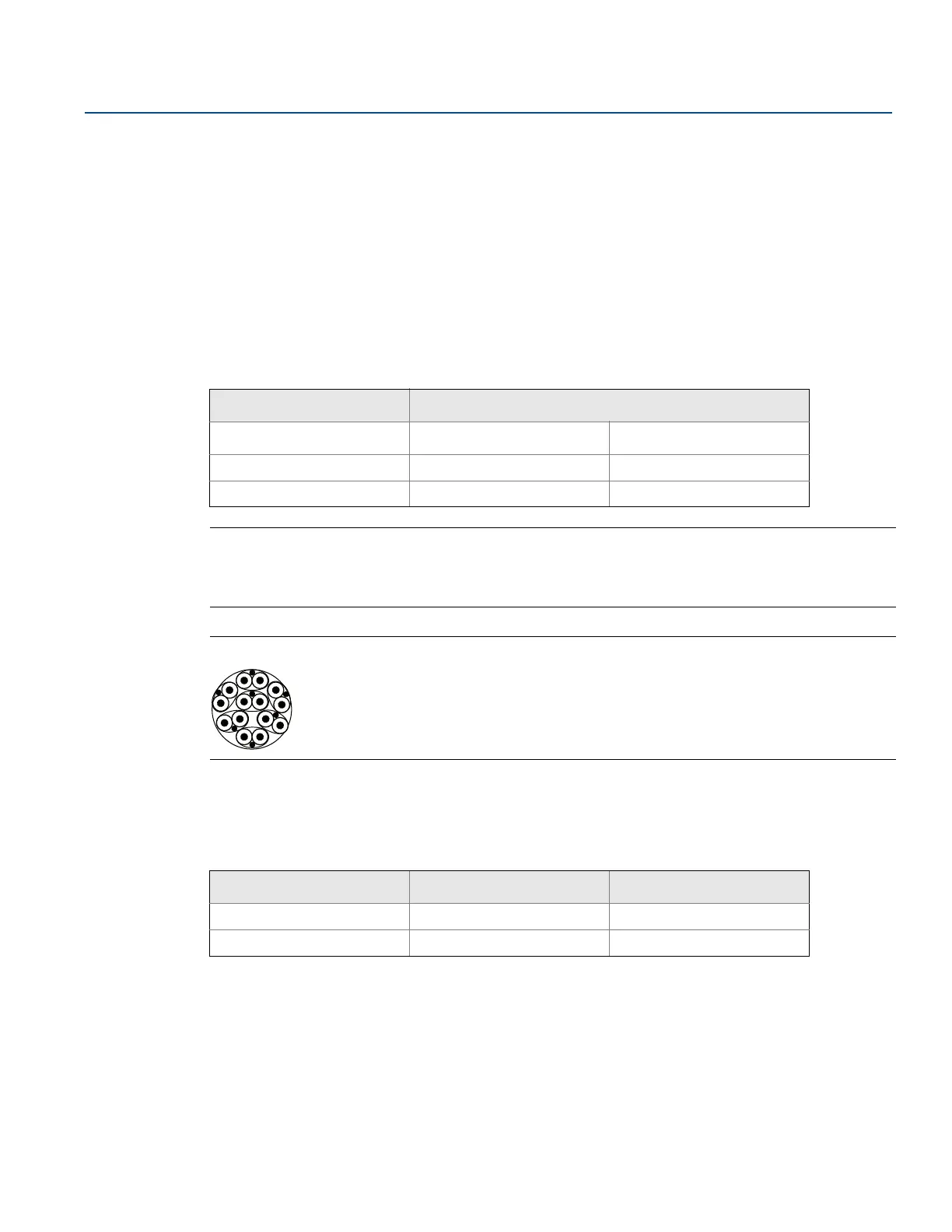
Wherever two or more TRL2 buses run alongside each other, sharing the same cable or conduit tube, use
twisted and shielded wire and ensure that each pair of bus wires is individually shielded in order to avoid
crosstalk.
Figure 3-3. Individually shielded pair cables minimizes crosstalk
Tab le 3 -3 shows typical cable types that can be used for connecting the TRL2 bus. Other cables of similar
type may also be used.
Table 3-3. Recommended cable standards for the TRL2 bus
RS485 bus
The RS485 bus should meet the following requirements:
twisted and shielded pair wiring
characteristic impedance of 120
maximum cable length 1200 m / 4000 ft at baud rate 9600 bps
Maximum distance Cross-sectional area
Minimum Maximum
3 km 0.50 mm
2
(AWG 20) 2.5 mm
2
4 km 0.75 mm
2
(AWG 18) 2.5 mm
2
Type Manufacturing standard Core size
Signal BS 5308 part 1, type 1 1 mm
2
Signal (armoured) BS 5308 part 2, type 1 1 mm
2
 Loading...