148
Reference Manual
00809-0100-2460, Rev DE
Service and Troubleshooting
October 2018
Service and Troubleshooting
6.27 Modem cards
6.27.1 RS232 and RS485
The RS232/485 modem card (see Figure 6-9 on page 149) can be used for RS232 or RS485
communication. Four switches are available to configure the card as specified in Tabl e 6- 6.
In case the card is configured for RS485 communication, the terminator must be activated (ON) when
the Rosemount
™
2460 is the last device on the bus.
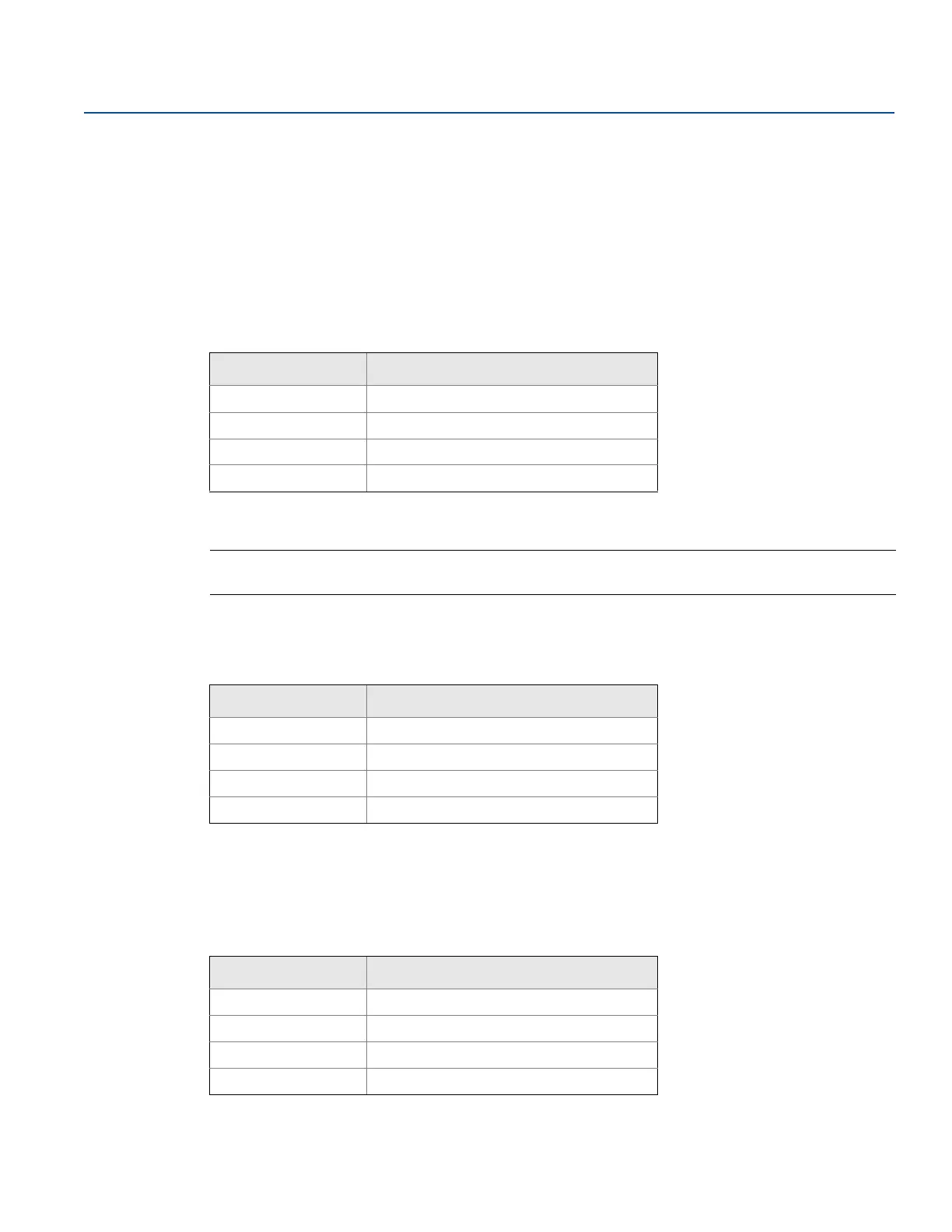
Table 6-6. Configuration switches
Note
Both the switches must be either ON or OFF position for proper operation and indication.
RS-232
Table 6-7. Configuration switches when using RS-232 communication
RS-485
Table 6-8. Configuration switches when using RS-485 communication
Switch Description
S1 RS-485 and RS-232
(1)
selection
1. When using the RS-232 interface the RS-485 termination switches (S3 and S4) must be
in OFF state
S2 RS-485 operation mode Half/Full Duplex
S3
(2)
2. Both S3 and S4 must be in ON or OFF state for proper termination or no termination
RS-485 termination ON/OFF (High side)
S4
(2)
RS-485 termination ON/OFF (Low side)
Switch RS-232 communication
S1 RS-232 (ON)
S2 (not applicable for RS-232)
S3
(1)
1. When using the RS-232 interface the RS-485 termination switches (S3 and S4) must be
in OFF state
OFF (RS-485 termination High side)
S4
(1)
OFF (RS-485 termination Low side)
Switch RS-232 communication
S1 RS-485 (OFF)
S2 RS-485 operation mode Half/Full Duplex
S3
(1)
1. Both S3 and S4 must be in ON or OFF state for proper termination or no termination
RS-485 termination ON/OFF (High side)
S4
(1)
RS-485 termination ON/OFF (Low side)
 Loading...