9
Reference Manual
00809-0100-2460, Rev DE
Overview
October 2018
Overview
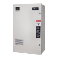
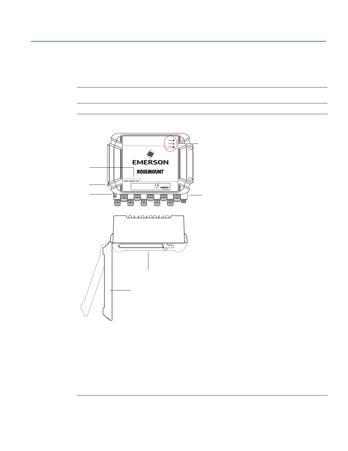
2.3 Components
This section shows the various parts of the Rosemount 2460 System Hub.
Note
The Rosemount 2460 System Hub is designed for use in non-hazardous areas.
Figure 2-3. Rosemount 2460 System Hub front and top view
A. Main label
B. Locking ring for securing lid
C. External ground terminal (M5 screw, flat, lug dimension max. 10 x 4 mm), page 28, page 39
D. Light Emitting Diodes (LED) for status and error messages, page 90
E. Cable entries (Nine (9) M20 x 1.5, Two (2) M25 x 1.5), page 28
F. Lid (can be removed by removing the locking ring)
G. Terminal compartment with communication boards and ports
2460-
TAG:
S/N:
MFG (yymmdd):
DEVICE ID:
MAINS: 100-250VAC 50/60Hz, 24-48VDC 20W
MADE IN GOTHENBURG SWEDEN
 Loading...