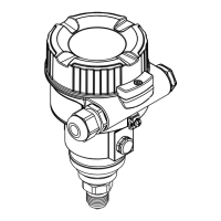
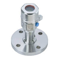
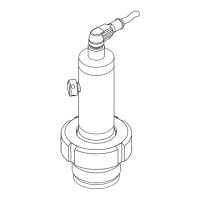
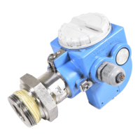
Cerabar M PMC51, PMP51, PMP55
94 Endress+Hauser
JIS flanges, connection dimensions as per JIS B 2220 BL, raised face RF
A0021680
D Diameter of flange
b Thickness
g Raised face
f Thickness of raised face
k Hole circle
g
2
Diameter of hole
d
M
Max. diaphragm diameter
Engineering unit mm
Flange
1) 2) 3)
Boltholes Diaphragm seal Option
4)
Nominal diameter Nominal pressure D b g f Quantity g
2
k d
M
Weight
[mm] [mm] [mm] [mm] [mm] [mm] [mm] [kg (lb)]
25 A 10 K 125 14 67 1 4 19 90 32 1.5 (3.31) KCJ
40 A 10 K 140 16 81 2 4 19 105 48 2.0 (4.41) KEJ
50 A 10 K 155 16 96 2 4 19 120 59 2.3 (5.07) KFJ
80 A 10 K 185 18 127 2 8 19 150 89 3.3 (7.28) KGJ
100 A 10 K 210 18 151 2 8 19 175 89 4.4 (9.7) KHJ
1) material: AISI 316L
2) The roughness of the surface in contact with the medium including the raised face of the flanges (all standards) made of Alloy C276, Monel,
tantalum, rhodium>gold or PTFE is R
a
< 0.8 µm (31.5 µin). Lower surface roughness on request.
3) The flange raised face is made of the same material as the process isolating diaphragm.
4) Product Configurator, "Process connection" section

 Loading...
