© EPRAD Incorporated
4) Status LED - This indicates the status of the on-board computer. If the computer is operating
properly, it will indicate one of three conditions.
1: A fast (.2 second) blink rate indicates the computer is working and communicating properly
with the eCNA-10 main control board.
2: A slow (1 blink ON, 2 seconds OFF) rate indicates since power up, the board has not
received data from the eCNA-10 main control board. The I/O is disabled.
3: A slow (2 blinks ON, 2 seconds OFF) rate indicates a communication timeout.
Communications were once established and subsequently lost. The I/O is disabled.
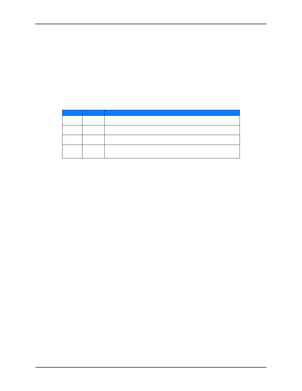
5) Option Jumpers - These jumpers are used for special configuration.
Jumper Position Description
OPT 1
1-2
2-3
Undefined. Reserved for future.
Undefined. Reserved for future.
OPT 2
1-2
2-3
Undefined. Reserved for future.
Undefined. Reserved for future.
OPT 3
1-2
2-3
Undefined. Reserved for future.
Undefined. Reserved for future.
OPT 4
1-2
2-3
Normal Mode. Use this setting when the board is used with an eCNA-10.
Emulation Mode. In this mode, the board emulates the 39331 Booth
termination board in order to be compatible with older CNA automations.
6) Optional Expansion Board - J1 and J2 socket strips are used for expansion boards. J2 supports
the 39436 Aux I/O board.
7) 12 Volt Power - TB5 (17-20) are the +12 volt power connections. This is normally used for
‘contact sense’ input wiring, but can be used to power any 12 volt device such as an external
relay. The supply is fused at 1/4 amp. LED 27 indicates the condition of the fuse.
8) Inputs - TB5 (1-16) are the low voltage isolated input connections. Inputs can be wired for
either ‘contact’ or ‘voltage’ sense. All inputs are de-bounced and require a minimum pulse
width of 0.5 seconds.
Input Range: 5VDC - 34VDC, 3.6VRMS - 24VRMS @ 20mA Max.
9) Low Power Relay Outputs - TB4 are the low power output connections. All relay contacts are
‘dry’ and require an external power source.
Contact Maximum Ratings: 30VRMS @ 2 Amps / 60VDC @ 1 Amp
10) Override Connections - P5, P6 and P7 headers are for the low power manual override cables.
11) High Power Relay Outputs - TB2 and TB3 are the high power output connections. The relay
contacts are ‘dry’ and require and external power source.
Contact Maximum Ratings: 250VRMS @ 10 Amps / 30VDC @ 10 Amps
137
eCNA-10 Operation and Installation Manual Version 1.270-00