© EPRAD Incorporated
4. Configuring the Unit
The eCNA-10 must be configured to operate on a network with various network devices and with the
booth and auditorium equipment.
4.1 Configuring the Main CPU Board
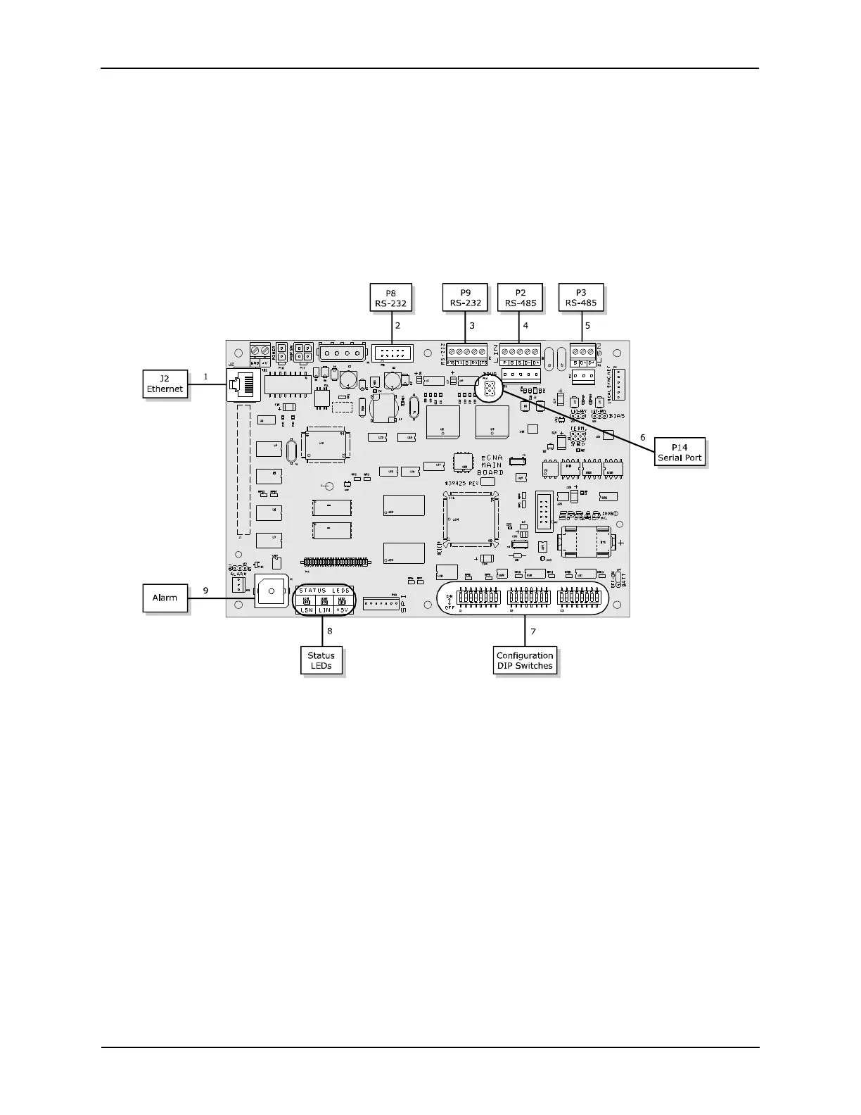
The Main CPU board (P/N 39425-1) incorporates several serial communication ports including an
Ethernet port. Each of these ports have specific purposes. There are 3 banks of DIP switches used for
basic system configuration. The LEDs provide an indication of power supply and serial
communications status.
1) Ethernet J2 a 10Base-T Ethernet RJ-45 connector.
2) RS-232 P8 is an RS-232 port used to set up the Ethernet parameters. The same parameters can
be set up from the web browser interface.
3) RS-232 P9 is an RS-232 port used for CAI channel 1 communications.
4) RS-485 P2 and P10 are the LIN (Local I/O Network) connections. Serial data and power support
the termination boards, dimmer control and any other LIN devices.
5) RS-485 P3 and P11 are connectors for the isolated RS-485 LSN port.
6) Serial Port P14 supports the CAI channel 3. It requires the optional 39446 RS-232 adapter
board.
7) Configuration DIP Switches S1 through S3 are used for eCNA configuration.
8) Status LEDs LED1 displays the status of the LSN and LED2 displays the status of the LIN. A fast
blink indicates that the eCNA is communicating with a network device. LED3 is the +5 volt
computer voltage.
11
eCNA-10 Operation and Installation Manual Version 1.270-00