C8-B/C12-B Service Manual Maintenance Disclosure Scope: Maintenance Trained Personnel Only
(C) Seiko Epson Corporation 2-289 Rev.1
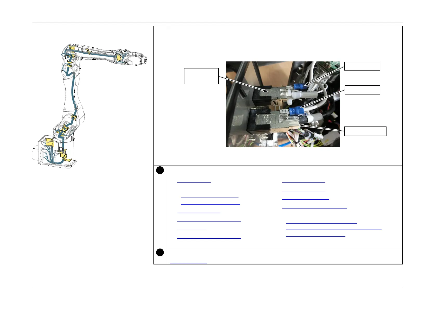
13. Connect the following connectors in accordance with the indications on the Connector
Plate.
• RJ45 connector: Ether
• F-sensor connector: F-sensor
POINT
After connecting the connectors, attach the Ground Wire to each connector.
Install the following parts.
• Gyro board 1
• J1 Motor unit
(M/C Cable Backward),
(M/C Cable Downward)
• Arm4 side cover (both sides)
• Arm4 maintenance cover
• Arm3 cover
• Arm3 maintenance cover
• Arm2 side cover (both sides)
• Arm1 side cover (both sides)
• Arm1 center cover
• Base Maintenance Cover
• Connector Plate
(M/C Cable Backward: C8L),
(M/C Cable Backward: C8XL, C12XL),
(M/C Cable Downward)
After assembly, perform calibration of each joint.
3.2 Calibration
Installing the Cable Unit